-
User fiber optic cable test below 24
Fiber testing is the process of verifying the performance of optical fiber cabling. This process includes a range of tests and measurements such as insertion loss, optical return loss, and fiber length. It encompass.
[PDF Version]
-
How many cores are typically in an optical fiber splice closure
Fiber splice enclosures protect delicate fiber optic connections from moisture, dust, and physical damage. They come in different types for various environments (indoor/outdoor), sealing methods (mechanical/heat shrink), and core capacities (12-96 cores). com are available from typical 12 core closures to 500 cores or more. The right choice depends on installation. The vertical dome fiber optic closure is a widely used solution for underground and direct burial applications. Ideal for network expansion and distribution, it securely houses fiber cables while. Dome Type 3 Port Fiber Optic Splice Closure Heat Shrinkable FOSC, LW-FOSC-DH-24A-3 Description: Fiber Optic Splice Closure, also named Fiber Optic Joint Enclosure, is [. ] Dome Type 4 Port Fiber Optic Splice Closure Mechanical Sealing FOSC, LW-FOSC-DM-48A-4 4 round ports 12 cores/tray, 6 Slots/tray. Mechanical fiber optic dome closure for max.
[PDF Version]
-
What are the common faults of fiber optic splice boxes
Dirty Fibers: Dust, oil, and residue reduce splice quality. Misalignment: Incorrect positioning of fibers leads to light leakage. Worn Electrodes: Old or contaminated electrodes. Despite their importance, fiber optic splice closure can experience a range of issues that can cause problems with network performance. Cable Damage One of the most common issues. There are bubbles or cracks in the joints during welding This situation may be due to poor cutting of the optical fiber, such as inclined end faces, burrs, or unclean end faces. It is necessary to clean the optical fibers before performing fusion splicing operations; another case is that the. Unlike active components, terminal boxes fail due to structural mismanagement, not electrical malfunction. Most instability originates from cable routing discipline, strain transfer, or enclosure sealing integrity. In this section, we will discuss these issues and how to troubleshoot them. Issues like signal loss, physical damage, and poor connections can degrade performance or cause complete outages.
[PDF Version]
-
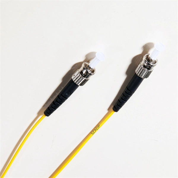
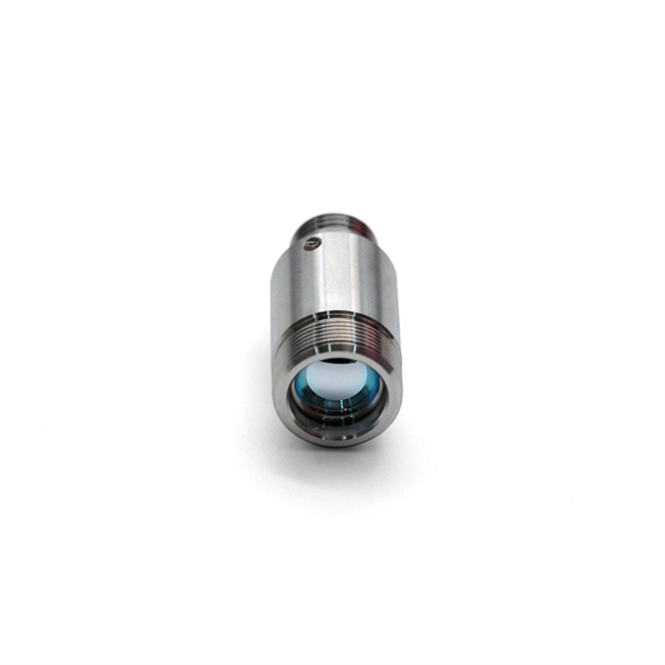
Function of Fiber Optic Cold Splice Terminal Connector
Fiber optic cold connection, also known as mechanical splicing, is a widely used method of connecting optical fibers in a network. Unlike fusion splicing, which uses heat to join two optical fibers together, cold connection uses mechanical means to create a stable and low-loss. Should you use connectors or splices? In this lesson, a long and very important one, you will learn about fiber splicing and termination. Fiber optic joints or terminations are made two ways: 1) splices which create a permanent joint between the two fibers or 2) connectors that mate two fibers to. Fiber optic joints or terminations are made two ways: 1) splices which create a permanent joint between the two fibers or 2) connectors that mate two fibers to create a temporary joint and/or connect the fiber to a piece of network gear. In this. Executive Summary: A fiber optic pigtail is one of the most commonly specified yet least understood components in structured cabling.
[PDF Version]
-
What is an aluminum alloy fiber optic connector closure called
The fiber dome closure OPGW has been developed for using with OPGWs (Optical Ground Wires) for jointing max. Aluminium Alloy ADSS OPGW Fiber Optical Splice Closure The metal joint box are applicable for connection protection of special optical cables,with the functions of direct and branch connection, with the maximum of 6 optical cables, which mainly for overhead rods and towers. It features in high mechanical strength, good airtight and anti-corrosive. Having been sealed with sealing ring and silicone, it could be opened, expansed, fixed, and connected repeatedly. Splices are generally placed in a splice tray which is then placed inside a splice closure or integrated into a fiber pedestal for OSP. Joint boxes are classified according to material classification: plastic joint boxes, aluminum alloy joint boxes, and stainless steel joint boxes. According to appearance, it can be.
[PDF Version]
-
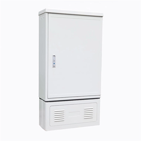
How many ports does the optical fiber splitter distributor have
Featuring 24 fiber ports, comprising 3 inlet, 16 outlets, this fiber optic splitter box ensures seamless connectivity across your fiber optic infrastructure. Cost Efficiency: A single OLT port can serve 8–64 ONTs via a splitter, reducing the number of OLTs, fibers, and deployment labor needed. Passive Operation: Splitters have no active electronics, so they require no power, cooling, or maintenance—lowering operational costs (OPEX) for ISPs. Indoor/Outdoor Wall Mounted, Single Door Fiber Distribution box is ideal for end terminations of fiber optic runs in residential or commercial buildings. Integral gasket seal provides IP65 level of protection. Pre-installed with 24 SC/APC simplex couplers and two 1x8 terminated SC/APC splitters, it effortlessly supports single-mode fiber optic. A fiber broadband provider typically determines and overall split ratio for the network, such as 1x32 or 1x64, and uses combinations of splitters to meet that ratio with each PON port. 1x32 splits were common in North America for G-PON architectures.
[PDF Version]
-
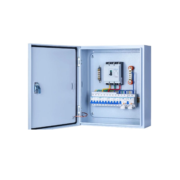
How to configure the number of ports on a fiber optic patch panel
Here's a step-by-step guide to help you properly arrange fiber optic patch panels in a data center environment. Before installation, assess your network's current and future needs: Use this information to select the appropriate patch panel type—rack-mounted, wall-mounted, or modular high-density. Fiber patch panels come in various configurations, including 12-port, 24-port, 48-port, 72-port, 96-port, and 144-port fiber distribution frames. These options cater to different network requirements and capacities. The most common configurations are 24 port fiber patch panel and 48 port fiber. ● The patch panel is a long-term solution that can provide high-density port connectivity solutions for 4x10 Gbps, 100 Gbps, 2x100 Gbps, 4x100 Gbps, 400 Gbps, 2x400 Gbps, and 4x400 Gbps breakout requirements. And label the ports to identify different cables so that technicians have clear instructions on what they need. Suitable to SC LC FC ST or other fiber connectors as requested, Meanwhile, 12, 24, 36, 48, 72, 96, 144 ports are available Mounted directly onto walls for space-saving installations.
[PDF Version]
-
Fiber Optic Splice Box Inspection Report
This template supports fiber optic splicing work by guiding teams through key documentation and quality checks. Record the job details (conducted on, prepared by, location) and the joint name, then capture photographic evidence of strength members, internal splicing across all trays and splitters. All Rights Reserved. fCONSTRUCTION QUALITY REQUIREMENTS FOR FTTP & SSP Work Orders This document provides Construction Technicians, Construction Managers, FTTP/SSP Vendors, and Inspectors with the essential information to ensure a quality build and to successfully pass an Outside Plant Inspection. Inspect the splice enclosure for any damage or defects. Verify that all components are accounted for. 5 dB and prevent costly network outages caused by contaminated connectors. They define a minimum baseline of quality and workmanshi for installing electrical products and systems.
[PDF Version]
-
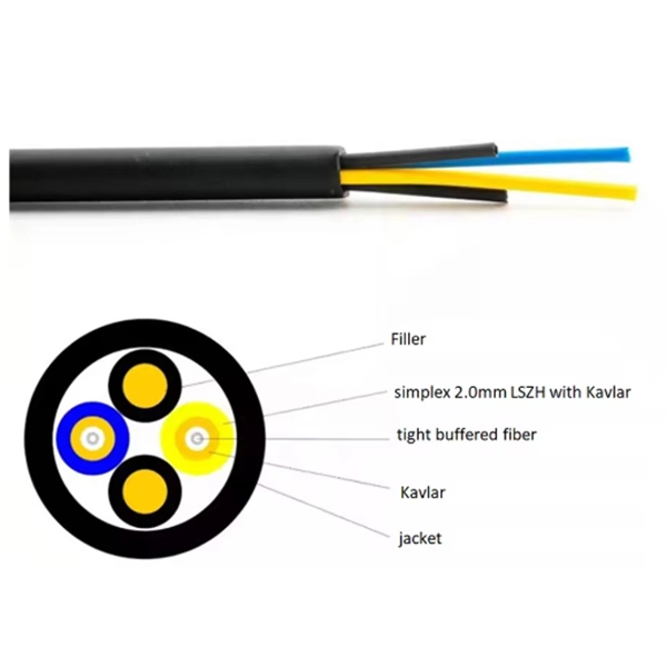
How to splice outdoor four-network-in-one optical cables
Watch a real technician demonstrate how to join optical fiber cable professionally using advanced fusion splicing techniques. moreSplicing fiber optic cable is an extremely important phase for making dependable, high-speed communication infrastructures. Regardless of the type of fiber network you're deploying, be it for telecom, enterprise data centers, or smart city infrastructure, fusion splicing provides the benefits of. Internal trays organize 4 cable ends for safe routing. Additionally, the enclosure is crush-resistant, designed for 16 splice holders. They withstand temperatures of 176 degrees Fahrenheit. The enclosure is ideal. In this guide, we cover the basics of fiber optic splicing, how to perform splicing using two different methods, and finally some best practices to perform good fiber splicing. What is Fiber Optic Splicing and Why is it Needed? – #1.
[PDF Version]
-
Reasons for the stretching and flattening of fiber optic cable splice closures
They protect spliced fibers, manage mechanical stress, isolate environmental exposure, and ensure long-term optical stability across feeder, distribution, and access layers. When closures fail, the consequences are rarely isolated: A reliable FTTH network is only as strong as its. Are you looking for ways to improve the performance of your fiber optic splices? If so, you've come to the right place. In this blog post, we'll examine the factors that affect splice performance, including intrinsic factors, extrinsic factors, and core diameter mismatch. Macrobends are. There are hundreds of different designs and options on splice closures. Some closures are designed for connecting several smaller cables to a larger one for breaking out the larger cable to. 25+Years Fiber cable Manufacturer, We are manufacturing the fiber core,fiber cable,data cable, patch cords. Our customers are including China Telecom,China Mobile,China Unicom. Despite their importance, fiber optic splice closure can experience a range of issues that can cause problems with.
[PDF Version]
-
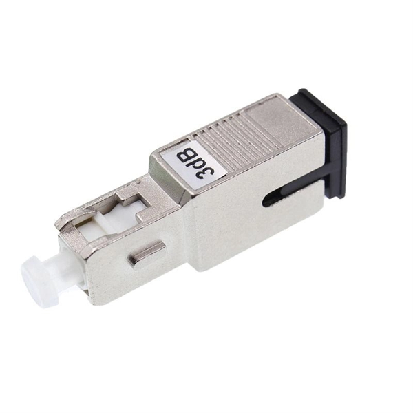
Multimode fiber optic splice loss standard
For multimode fiber, the loss is about 3 dB per km for 850 nm sources, 1 dB per km for 1300 nm. 5 dB/km max per EIA/TIA 568) This roughly translates into a loss of 0. Splicing is required to create a continuous path for light transmission from one fiber to another. Two different methods exist for splicing fibers: Typical splice loss values (the measure of loss in optical power across the splice point) are usually lower for fusion splices (typically less than 0. 1. To be able to judge whether a fiber optic cable plant is good, one does a insertion loss test with a light source and power meter and compares that to an estimate of what is a reasonable loss for that cable plant. The estimate, called a "loss budget" is calculated using typical component losses for. Acceptable dB loss for fiber depends on the component you're measuring: a single mated connector pair should lose no more than 0. 75 dB, a fusion splice should stay under 0. 5 dB per kilometer depending on the type and wavelength. The Contractor must utilize the correct equipment and testing techniques to gain acceptance, or the work cannot be approved. Optical fiber splicing is a critical.
[PDF Version]
-
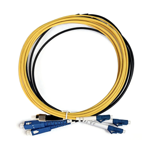
How to splice 96 fiber optic cable
Learn how to splice fiber optic cable using fusion splicing with this complete step-by-step guide. Includes tools, best practices, loss standards (ITU-T G. 652), cost analysis, and FAQs for network engineers and installers. Regardless of the type of fiber network you're deploying, be it for telecom, enterprise data centers, or smart city infrastructure, fusion splicing provides the benefits of. Think of a fiber optic cable splice as the seamless stitching that keeps data flowing through the delicate threads of a network—like a master tailor joining fabric with precision. more Splicing of Optical Fiber Cable 96 Core inside MUFF/ Splice Tray. This process requires precision, patience, and a deep understanding of the delicate nature of optical fibers.
[PDF Version]
-
Installation of outdoor fiber optic cables in buildings
Plan your outdoor fiber installation carefully by surveying the site, choosing the right cable type, and following FOA and OSP standards to ensure reliability. Select the best installation method—direct burial, aerial, conduit, or underwater—based on your environment and future network needs. Use. This guide explores different types of fiber optic cable, including indoor fiber optic cable and outdoor fiber optic cable, and outlines best practices for installation in different settings. If you're unfamiliar with the fundamental concepts of fiber optic technology, we recommend reading our. The Fiber Optic Association, Inc. The charter of the FOA was to promote professionalism in fiber optics through education, certification, and. This article will provide an in-depth analysis of outdoor cable types, key selection criteria, core installation steps, critical precautions, as well as subsequent testing and maintenance guidelines, helping you build a robust and durable outdoor optical communication link. The cable should be bent as little as possible.
[PDF Version]
-
How to connect outdoor multimode fiber optic cables in Israel
This article will provide an in-depth analysis of outdoor cable types, key selection criteria, core installation steps, critical precautions, as well as subsequent testing and maintenance guidelines, helping you build a robust and durable outdoor optical communication link. What Is Outdoor Fiber. This guide explores different types of fiber optic cable, including indoor fiber optic cable and outdoor fiber optic cable, and outlines best practices for installation in different settings. Whether you're connecting a data center or simply linking your home office to a shop, it's important to understand the fundamental aspects of fiber optic. We have "outside plant" fiber optics as used in telephone networks, CATV, metropolitan networks, utilities, etc. or "premises" fiber optics as found in buildings and campuses.
[PDF Version]
-

How to calculate fiber optic splice attenuation
The calculator essentially performs the following calculation: Total Attenuation (dB) = (Attenuation Coefficient * Cable Length) + (Number of Connectors * Connector Loss) + (Number of Splices * Splice Loss)The calculator essentially performs the following calculation: Total Attenuation (dB) = (Attenuation Coefficient * Cable Length) + (Number of Connectors * Connector Loss) + (Number of Splices * Splice Loss)This calculator helps you estimate the total attenuation (signal loss) in a fiber optic cable link. Here are the details and instructions about each field and how they contribute to the calculation: 1. Attenuation Coefficient (dB/km): This value represents the inherent signal loss per kilometer of. Model optical links with practical engineering inputs fast. Review attenuation, splice, connector, and splitter effects. Check total loss, power margin, and feasibility clearly.
[PDF Version]
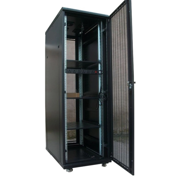
Telecom Racks & Cabinets
19-inch racks, wall-mount cabinets, open frames with high load capacity and seismic rating.
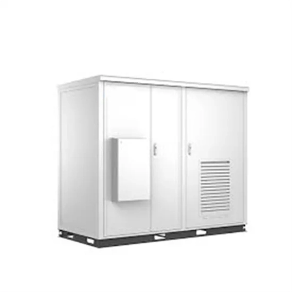
Outdoor Climate Cabinets
IP55/IP66 outdoor enclosures with integrated cooling/heating, -40°C to +55°C operation.
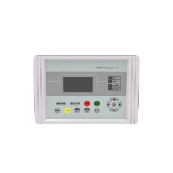
Smart PDUs & Power Distribution
Intelligent PDUs with remote monitoring, per-outlet switching, and environmental sensors.
Shelters & Network Cabinets
Prefabricated telecom shelters, emergency comms shelters, and network cabinets with cable management.