-
Fiber optic patch cord end face defects
It's crucial to inspect, clean, and reinspect fiber end faces before mating connectors — whether on patch cords and trunks within the network or on the test reference cord you connect to your tester. In high power transmission, a contaminant may burn and fuse the dirt with the silica material of. Fiber optic inspection microscopes vary in magnification from 30 to 800 power, with 100-400 power being the most widely used range for connector ferrule inspection. In this blog post, we'll take a deep dive into the key performance tests for fiber optic patch cords — polarity verification, insertion loss and return loss measurement, 3D interferometric endface metrology, and endface inspection — along with the relevant standards, equipment, methodologies, and.
[PDF Version]
-
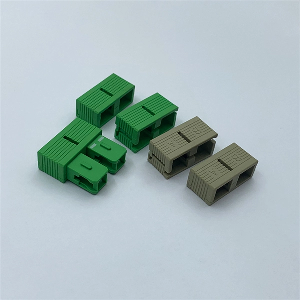
Grade A fiber optic fast connectors at the end face offer good performance
These fiber optic connectors offer terminations without any hassles and require no epoxy, no polishing, no splicing, no heating and can achieve similar excellent transmission parameters as standard polishing and splicing technology. Optical fiber connectors are fundamental components in modern communication networks, ensuring reliable signal transmission. Standards such as IEC 61300-3-47. The differences between optical fiber grades A, B, C, and D primarily pertain to the quality of the fiber end-face, which significantly impacts performance metrics such as insertion loss (IL) and return loss (RL). Selecting the right connectivity requires a clear understanding of fiber end-face types and their compatibility—factors essential to maintaining. It's crucial to inspect, clean, and reinspect fiber end faces before mating connectors — whether on patch cords and trunks within the network or on the test reference cord you connect to your tester.
[PDF Version]
-
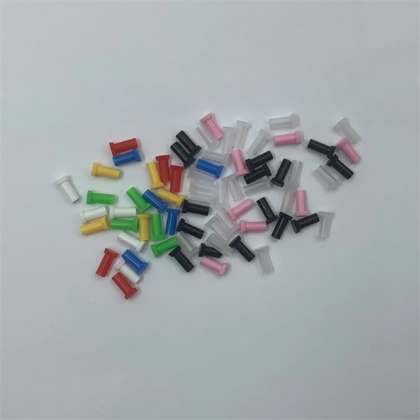
Flame-retardant installation solution for electric cleaning pen on fiber optic end face in Vietnam
Since electrostatic discharge (ESD) is a concern during a 'dry' clean, this kit contain cleaners specifically formulated to dissipate static when the end-face is pulled across a cleaner surface or a stick inserted into an adapter. We offer pre-stocked kits with a variety of cleaning tools and can also build you custom kits to meet your specific application needs. Push-type cleaners feature an. There are four families of fiber optic connector cleaning products that essentially wipe contaminants off the end faces. They can be used in the factory or the field. A fifth family includes electrical bench-top cleaners. The article analyzes contamination sources and their optical impacts, presents detailed tool selection criteria with comparison tables for. Cleaning fiber optic connectors is fast, easy and reliable with our highly engineered solvents, lint-free swabs, precision wipes, and cleaning platforms. It works in three stages: spraying cleaning solution to dissolve contaminants, injecting dust-free gas to dislodge them, and absorbing exhaust and debris.
[PDF Version]
-
Fiber Optic Patch Cord End Face Inspection Techniques
Endface inspection focuses on the visible quality of the polished fiber surface and surrounding ferrule area. You use a fiber microscope or automated inspection scope to check for contamination, pits, chips, cracks, and scratches. Even a small dust particle or scratch on the endface can increase insertion loss, reduce return loss, and introduce random link instability. In FTTH, ODN, and data center environments, you rely on consistent. That is why relying on International Electrotechnical Commission (IEC) industry standards and innovative inspection equipment is the most reliable way to ensure automatic, consistent, and repeatable certification of fiber cleanliness based on specific acceptance criteria. Fiber Contamination, Cleaning and Inspection. This article outlines the specific. 📦 For purchasing, use the RP Photonics Buyer's Guide for fiber endface inspection. It provides an expert-curated supplier directory, buyer-focused technical background information, and structured selection criteria to support professional procurement decisions. Fiber optics is generally quite.
[PDF Version]
-
Is the fiber optic channel anomaly at either end
No matter how your devices are connected, achieving polarity in fiber optics means that the fiber optic link's transmit signal (Tx) on one end of the channel must match or align with the corresponding receiver (Rx) on the other end. Polarity Overview Two. The Relevance Inspector will open in the Coveo Administration Console. Because there are many ways to connect devices using fiber optics, there's no “right” way to achieve fiber polarity. These regions are designed to host sensitive data and regulated workloads, ensuring compliance with stringent U. Utilizing SNR, our approach swiftly identifies soft anomalies, aiding early failure detection.
[PDF Version]
-
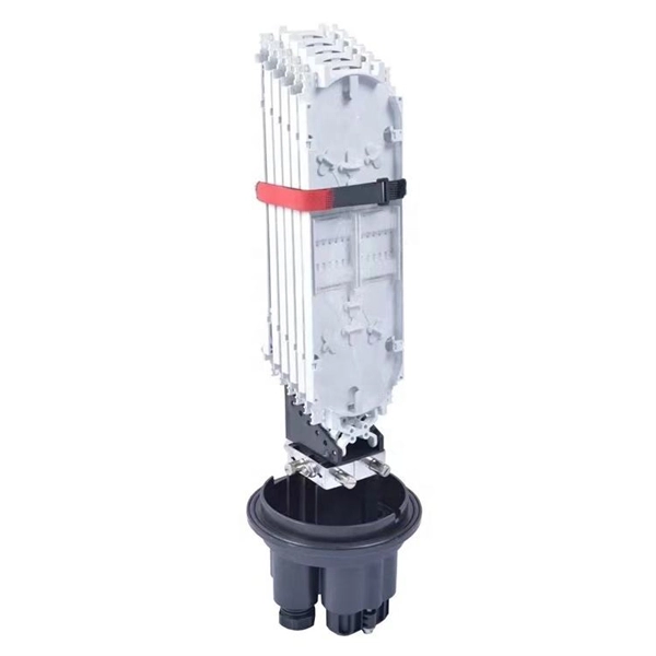
How to configure a fiber optic terminal box as an end
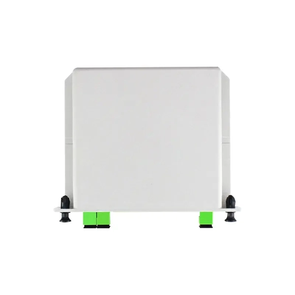
Learn how to install a fiber optic termination box step-by-step for FTTH projects. Covers mounting, splicing, routing, labeling, and testing for indoor/outdoor use. Installing a fiber optic termination box is one of those jobs that looks simple on paper, but it's. The fiber termination box is an interface between the fiber cable from the line side and the pigtails to be passed to the fiber distribution frame. A fiber pigtail is a specific hardware connection used for cable termination. It functions as a junction between the incoming fiber cable and the outgoing customer-side fiber cable, where one fiber can be spliced, patched. Fiber Termination Boxes (FTBs) are crucial components in fiber optic networks, facilitating the termination, connection, and management of optical fibers. Proper installation and maintenance of FTBs are essential to ensure the reliability and performance of the network infrastructure. It serves as a termination point for optical fibers, providing a secure and organized space for connecting and managing fiber optic cables. FTBs play a vital role in ensuring the.
[PDF Version]
-
How to view the other end of the fiber optic cable
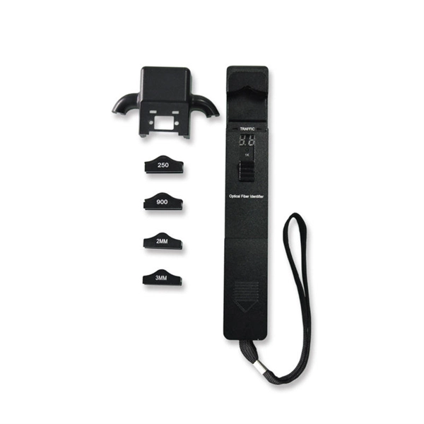
To trace fibers using the fiber optic tracer or VFL, connect the fiber to the output connector of the unit. The light output will be visible to the eye at the other end of the fiber. It's a cost-effective and. Testing newly installed fiber optic cables with a flashlight is a quick and simple method.
[PDF Version]
-
Why can t the fiber optic panel face upwards
A more common cause is poor field termination that results in air gaps and high insertion loss or scratches, defects and contamination on the end face of the connector. These high-speed, high-capacity communication networks are increasingly replacing copper cables, offering superior performance and. When issues like signal loss, slow speeds, or intermittent connectivity arise, systematic troubleshooting is key. This guide will walk you through diagnosing and resolving common fiber network issues efficiently. Why Do Fiber Networks Fail? Despite their robustness, fiber networks can fail due to:. Problems within a fiber link can occur due to a wide variety of reasons. A very common problem is that a connector is not fully engaged - often hard to notice in a crowded patch panel. Or it could be caused by the quality of the connector itself, such as poor end-face geometry that doesn't pass the. However, even the most advanced fiber systems are not immune to issues that can disrupt service—from signal degradation to physical damage. Attenuation results in a weakened signal strength.
[PDF Version]
-
Loose fiber optic cable back end of router
Calculate end-to-end loss from cable length, connector and splice counts, and known component losses; verify with a light source + power meter (OLTS). This guide lists the actual, field-proven problems technicians encounter most often and gives step-by-step troubleshooting actions you can copy into your maintenance routine. Keep this article tightly focused on practical fixes — no speculation, no unrelated background — so you can resolve faults. Fiber optic networks are celebrated for their speed and reliability, but even the best systems can encounter problems. These networks are the backbone of modern data transmission, offering incredible speeds and bandwidth. However, even the most robust systems can. Most common fiber optic cable problems are fixable—often with a bit of know-how and the right approach. Let's dive into the most frequent headaches, how to spot them, and, most importantly, how to get your network back on track. Fiber optic cables are the unsung heroes behind lightning-fast data.
[PDF Version]
-
Should the other end of the fiber optic patch cord be fused
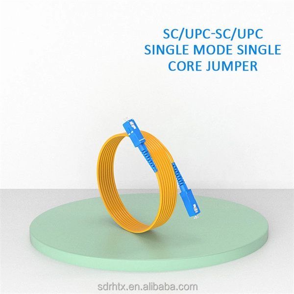
Once you've selected your pigtail, the bare fiber end needs to be permanently joined to the incoming cable fiber. This is usually the shortest. Traditionally, fiber links are made where pairs of fibers are crossed between patch panels so fiber 1 at one patch panel will be connected to fiber 2 at the patch panel on the other end, fibers 3/4. Thus, when connecting patchcords, fiber 1 (or the odd numbered. Correct patch-cord installation is essential for maintaining low insertion loss, stable return loss, and long-term reliability in both indoor and outdoor fiber networks. The preparation process is far more than just stripping away layers of protective coating. According to data from NS Comm's Fiber Performance Lab (2024 Q4 Test Report), poor installation practices can cause up to 2. 5 dB additional signal loss.
[PDF Version]
-
Crystalline Silicon for Optical Fiber Communication
Silicon-core fibres have unlocked new regimes of mid-infrared transmission, on-fibre Raman amplification and nonlinear wavelength conversion, finding relevance in gas sensing, biomedical diagnostics, high-power laser delivery and all-optical signal processing. Silicon-core optical fibres represent a convergence of semiconductor photonics and conventional fibre technology, embedding a crystalline silicon or silicon–germanium alloy core within a glass cladding. This architecture combines the high refractive index contrast and pronounced nonlinear response. Polycrystalline silicon core optical fibers have been fabricated by modified thermal annealing of amorphous silicon chemically deposited at high pressure. The resulting fibers have small-diameter cores, a geometry advantageous for optical guidance. Moreover, the combination of chemical deposition. Novel core fibers have a wide range of applications in optics, as sources, detectors and nonlinear response media. Optoelectronic, and even electronic device applications are now possible, due to the introduction of methods for drawing fibres with a semiconductor core. Here we explore the underlying.
[PDF Version]
-
Partially coherent light from multimode fiber
Excitation of a multimode fiber with a focused spatially coherent light of finite bandwidth results in a partially coherent light at the output of the fiber. We study the spatially incoherent light generated by a multimode fiber (MMF) in the application of image projection designed for the ultracold-atom experiments., entanglement) and be leveraged for advanced imaging and sensing modalities (e., in. Improving illumination uniformity is one of the most important steps to restrain the influence of the atmospheric turbulence on free-space optical communication. In this paper an optical structure.
[PDF Version]
-
Ranking of Fiber Optic Communication Lens Distributors
In 2025, as the industry shifts toward 800G, 1. 6T, and energy-efficient photonics, a handful of companies are defining the future of this essential technology. Here are the Top 10 leading companies in the global optical transceiver market, driving innovation, scalability, and. The figure below illustrates the changes in the TOP10 list of optical transceiver suppliers over the last 15 years. A majority of the Japanese and US-based suppliers exited this market by 2020, while Chinese vendors improved their rankings. Innolight and Eoptolink focused their business on service. From 5G networks and AI-powered data centers to cloud computing and fiber-to-the-home (FTTH) applications, optical transceivers play a critical role in enabling seamless and high-bandwidth communication. The highest number of Fiber optic products suppliers in California are in Santa Clara and Milpitas with 4 businesses and 3 businesses. Coherent Corp. (formerly known as II-VI Incorporated) is a global leader in engineered materials and optoelectronic components, serving diverse markets such as telecommunications, industrial manufacturing, and life sciences.
[PDF Version]
-
How to calculate the number of ports on a fiber optic patch panel
The fundamental calculation formula is: Total patch cords = Total number of device ports × Connection factor Where the connection factor depends on the connection method: 2. Scenario-Based Calculations The redundancy factor is typically 0 (no redundancy) or 1 (1:1 redundancy). Premium-Line 19” Rack mountable fiber optic patch panel is designed for both patching and splicing, accepts whole range of adapters including SC, ST, FC, LC adapters. 2 * Rear cable entries accommodate cables with diameter below 10mm. These options cater to different network requirements and capacities. Network architects and procurement managers must now evaluate patch panels not merely. Follow TIA-942 or ISO/IEC 11801 standards for structured cabling. It is important to know the.
[PDF Version]
-
Fiber Optic Cable Tractor Manufacturer
is a global leader in the design and manufacture of fiber optic and specialized copper wire manufacturing equipment. BM-Rosendahl is the global supplier of production equipment for lead-acid and lithium-ion batteries. Our relentless focus on quality, combined with our advanced pre-testing process, ensures your new equipment will require minimal commissioning time and will last for decades. 40 Years in Business (and Counting) 7 Days Average Commissioning Time 37 Countries Using Our Machines Anybody up for a trip. www. Typically, one or two machines can install FiberTRAX on pavement at a remarkable speed of up to 1,000 feet (305 meters) per. The RLH CORE cabinet is made from high-grade, powder-coated, aluminum alloy, with hinged doors, 3-point door latches, weatherproof seals, and a door-alarm switch. This 4RU fiber patch panel holds up to 12 LGX compatible fiber adapter plates, fiber splice trays, and is ideal for installation in a. Wire & Plastic Machinery Corp.
[PDF Version]
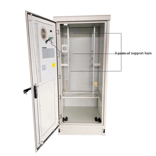
Telecom Racks & Cabinets
19-inch racks, wall-mount cabinets, open frames with high load capacity and seismic rating.
Outdoor Climate Cabinets
IP55/IP66 outdoor enclosures with integrated cooling/heating, -40°C to +55°C operation.
Smart PDUs & Power Distribution
Intelligent PDUs with remote monitoring, per-outlet switching, and environmental sensors.
Shelters & Network Cabinets
Prefabricated telecom shelters, emergency comms shelters, and network cabinets with cable management.