-
Which mode to choose for fused fiber optic pigtails
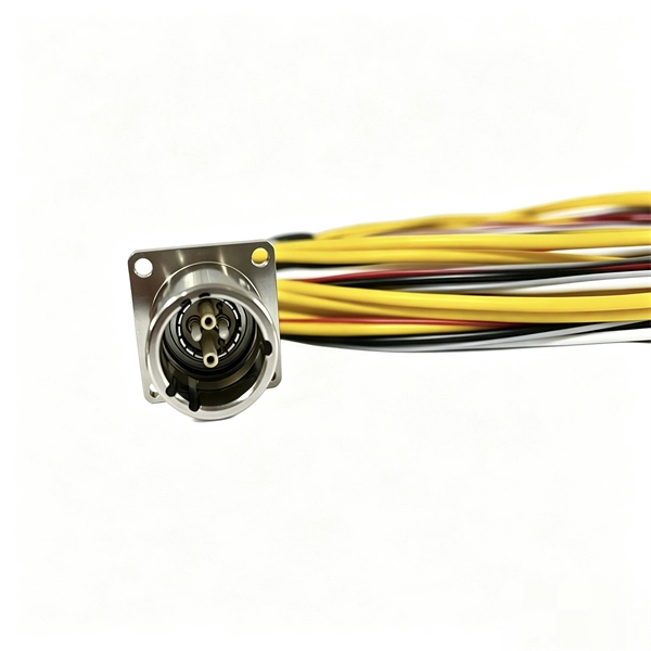
Fiber Type Choose single-mode for long-distance transmission and multimode for shorter runs. Connector Compatibility Match the connector (LC, SC, ST, etc. Fiber Count Select based on network scale—higher. Executive Summary: A fiber optic pigtail is one of the most commonly specified yet least understood components in structured cabling. Get the wrong connector type, the wrong polish, or skip proper fusion splicing technique—and you're looking at elevated signal loss, increased back reflection, and a. Fiber optic pigtails come with different connectors depending on your equipment: 3. Based on Fiber Count From your provided page, common options include: Higher fiber counts are ideal for data centers and high-density installations. You plug it into a switch, router, or patch panel. Protection Pigtail: Usually has a 0. Fiber optic pigtails are used to terminated fiber optic cables via fusion splicing or mechanical splicing as shown in the picture.
[PDF Version]
-
Remaining fiber cores in optical cable
First, clearly understand the number of wiring points and calculate the number of switches. Whether the connections between switches are stacked is also one of the considerations. Stacking: If the core switch i.
[PDF Version]
-
How to select the number of optical fiber cores
The number of optical cores in an optical fiber is the total number of equipment interfaces multiplied by 2, plus 10% to 20% of the spare quantity, and if the communication mode of the equipment has serial communication and equipment multiplexing, you can reduce the number of cores. This article will walk you through the basics of fiber optic cores and provide practical guidance for selecting the suitable fiber optic cable to meet your networking needs. Made from either high-quality. Fiber optic cables consist of multiple thin strands of glass or plastic, known as “cores. ” These cores carry the data signals via light. The number of. Common fiber cores include 1 core, 2 cores, 6 cores, 8 cores, etc.
[PDF Version]
-
How many cores of optical fiber cable does Indonesia use
The deployed fiber-optic cable is based on Nexans' 24-core unrepeatered (URC-1) design. Near the shore, at water-depths below 20 meters, it will feature a double-armored (DA) construction for extra protection against damage from shipping and fishing activities. Telecommunication Statistics Indonesia presents data on the development of the telecommunications sector in Indonesia, which includes internet penetration rates, ownership of information and communication technology (ICT) facilities, usage patterns, as well as data on telecommunications networks. Indonesia - how many cores do I need for fiber optic cable internet connection, 1500 meters / 5000 feet How many cores do I need? I would run the cable myself above ground out of reach, using existing poles. This technician is trying to scam me with the cable (normal here). I am guessing I need. Indonesia Fiber Optics Market: Import Trend Analysis In the Indonesia fiber optics market, the import trend showed a growth rate of 0. The Palapa Ring project is also summarized, which aims to connect over 33 provinces and 460 districts across the. NEC Corp. For depths between 20 and 200 meters.
[PDF Version]
-
How many fiber optic cores does a fiber optic patch cord contain
Multi-core patch cords are fiber assemblies containing multiple fibers within a single cable jacket, typically available in 4, 6, 12, and 24-fiber configurations. These assemblies are widely used in ODN distribution frames, data center racks, MDU risers, and fiber management systems where higher. Fiber cores are the heart of fiber optic cables, transmitting light signals that carry data. Made from either high-quality glass or plastic, the core plays a critical role in determining the cable's performance. Fiber optic patch cords (also known as fiber optic connectors) are fiber optic cables fitted with connector plugs at both ends, which are used to achieve the optical path. Connecting fiber optic cables to patch panels may seem like a straightforward task, but improper connections can lead to signal loss, decreased network efficiency, and even costly repairs. That's why understanding the proper techniques and tools for this process is essential.
[PDF Version]
-
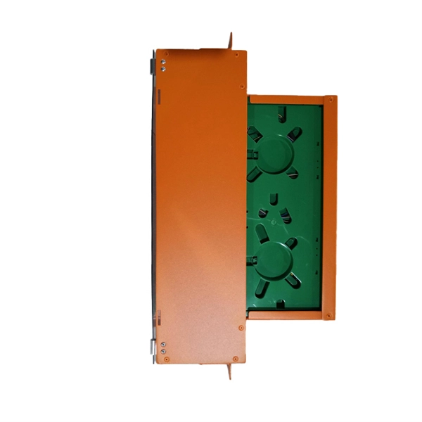
How to calculate the number of pigtails in a fiber distribution box
This guide explains how to evaluate fiber termination box capacity correctly, including fiber count, port configuration, splitter accommodation, and future growth. Many buyers assume “capacity” simply means the number of adapter ports on the front panel (for example, 8 ports or 16 ports). In. A fiber optic pigtail is a short, usually unjacketed, optical fiber cable that has a factory-installed connector on one end and a length of exposed fiber at the other. The connector end can be linked directly to network equipment, while the exposed end can be spliced to another fiber optic cable. Thus, a fiber termination box is used to terminate the optical fiber. Fiber termination box (FTB), also known as optical terminal box (OTB), generally refers to a distribution box specially designed for fiber cable management (fiber patch cables/pigtails) in FTTH applications. The ODF consists of a metal housing, cable entry ports.
[PDF Version]
-
What to do if fiber optic cold splices have high attenuation
When attenuation rises, you see reduced data speeds and higher error rates. Learn to use the OTDR to identify contamination, micro-bends, and poor splices, ensuring your 400G network links remain within budget. When a critical 400G link fails to establish or performs intermittently, the root cause is almost always excessive fiber optic attenuation. > You can solve this with simple steps. Clean Fiber Optic connectors often to stop dirt and dust. Dirt and dust can make. Fiber optic attenuation means signals get weaker as they move in optical fibers. Things like impurities in the fiber core and reflections at the core-cladding edge cause this drop. Reliable fiber optics depend on minimizing fiber signal loss for better network efficiency, data integrity, and longer transmission. This measurement helps determine the efficiency of a fiber optic system.
[PDF Version]
-
How to reinforce fiber optic pigtails for aesthetics and pricing
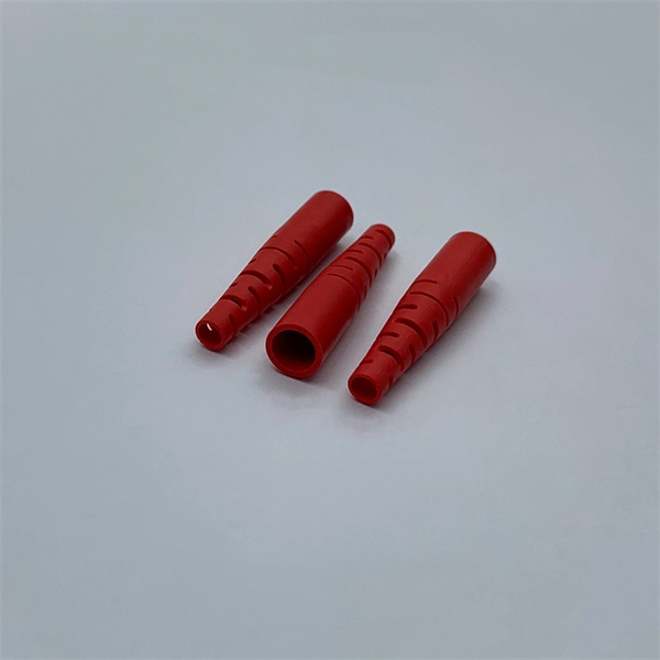
In this detailed video, we'll walk you through the fiber optic pigtail splicing process — from preparation to final testing. Executive Summary: A fiber optic pigtail is one of the most commonly specified yet least understood components in structured cabling. Get the wrong connector type, the wrong polish, or skip proper fusion splicing technique—and you're looking at elevated signal loss, increased back reflection, and a. Field-terminating connectors is a meticulous, high-pressure process where even a tiny mistake can force you to cut the fiber and start all over again. This is exactly why most professional installers have moved away from field-termination and toward splicing. This process requires precision, patience, and a deep understanding of the delicate nature of optical fibers.
[PDF Version]
-
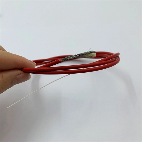
How high a temperature can single-mode optical fiber withstand
The high numerical aperture of these SM optical fibers guarantees low attenuation values even with narrow bending radii and in coils. Single-mode fibers with a carbon, acrylate, or polyimide coating that can withstand the highest stress and temperatures of up to 300°C. Optical fiber's ability to withstand extreme heat and cold directly impacts signal integrity, network reliability, and maintenance costs, especially in harsh environments like industrial facilities, outdoor installations, and data centers. As businesses increasingly rely on robust digital communications, understanding the environmental factors affecting fiber optic cables, particularly. In this work, we analyze the thermal effects occurring in optical fibres, such as the coating heating due to high power propagation in bent fibres and the fibre fuse effect. Thanks to their fluorinated. The working temperature of a standard fiber optic network cable is -40 º C to+75 º C. Please consult the manufacturer for specific information.
[PDF Version]
-
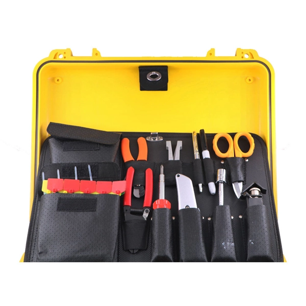
What to do if fiber optic pigtails are difficult to strip
Some strippers are especially bad for left-handed people, making it hard to strip fibers without breaking them. And make sure you have good lighting. Those are problems anyone can identify with visual inspection and learn from the inspection how to do it correctly in the future. Fiber optic connector. Executive Summary: A fiber optic pigtail is one of the most commonly specified yet least understood components in structured cabling. Get the wrong connector type, the wrong polish, or skip proper fusion splicing technique—and you're looking at elevated signal loss, increased back reflection, and a. Field-terminating connectors is a meticulous, high-pressure process where even a tiny mistake can force you to cut the fiber and start all over again. This is exactly why most professional installers have moved away from field-termination and toward splicing. Align and fuse the pigtail fiber with the main. Introduction Termination refers to the process of installing connectors on the ends of a fiber or fibers in a fiber optic cable.
[PDF Version]
-
How many pigtails should a 48-port fiber optic patch panel have
The 48-port rack mount fiber patch panel supports flexible configuration with up to 8 separate adapter plates (6 adapters per panel) and accommodates 48 or 96 fiber counts using pigtails. 16) LANS, loaded, with pigtails OS2 Products F. O Corning Patch panel. The LANscape® housing family was designed for various applications in 19-racks and main distribution frames. The fixed or sliding housings can be equipped with industry common adapter types in different fiber categories and are suitable for direct field termination, fusion splicing with pigtails as. The ECFPP-SL01-24LC2 from ShowMeCables is a 1U rack mount patch panel that comes populated with 24 Duplex LC/UPC couplers along with 48 LC/UPC 0. This panel also includes a smooth sliding drawer type pull out system.
[PDF Version]
-
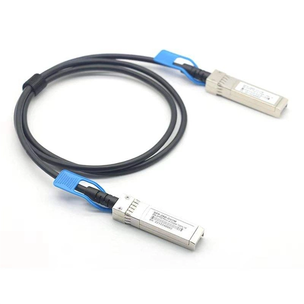
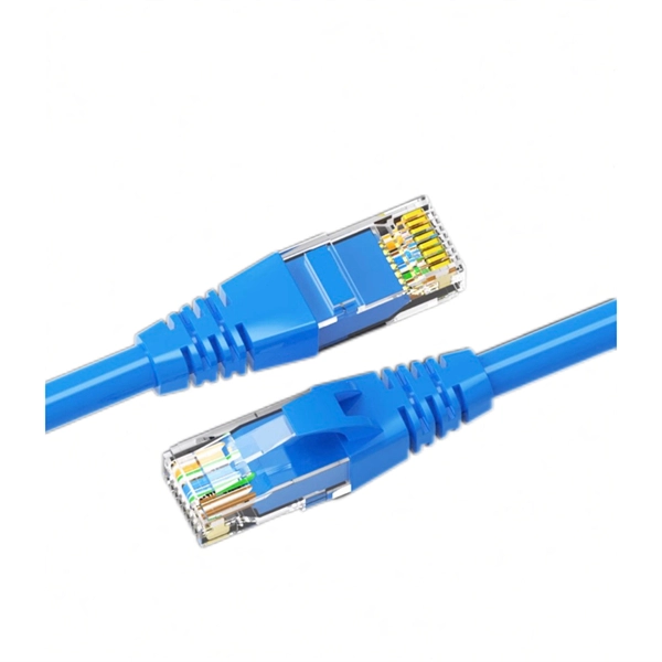
Switch Ethernet to Fiber Optic Port Mode
In this article, we'll explain how to connect multiple Ethernet switches using fiber optic cables and the equipment required for this to work. Network topology refers to the way in which the links and nodes of a network are arranged in relation to each other. The TC3212 10/100Base-T Ethernet Fiber Optic Converter is specifically designed for long distances and can extend LAN segments up to 80 kilometers and maximize bi-directional, fiber optic cable usage. It provides a 100Base-FX port that combines Ethernet Switching with the benefits of fiber optic. VERSITRON manufactures a wide range of fiber optic switches that provide links for your 10Base, 100Base, 1000Base Gigabit, and 10 Gigabit networks simultaneously. In real networks such as campuses, factories, metro POPs converters let you reuse existing switches and still run fiber for long distance, EMI immunity. Check each product page for other buying options. 5G, and gigabit options to expand your bandwidth. The SEL-2725 is an unmanaged five-port switch and copper-to-fiber-optic media converter. Single- or multimode fiber optics are available to accommodate a wide range of utility and industrial applications.
[PDF Version]
-
What to do if the fiber optic cable splice loss is too high
If high loss persists, inspect the splicer's alignment system. Clean the V-grooves and objective lenses with appropriate cleaning sticks and isopropyl alcohol. Dirt or dust on the fibre ends is one of the most common causes of high splice loss. Fusion splicers have settings that must be tailored to your fibre type and condition. Modern fiber optic networks usually keep splice loss low, as shown below: You should know that each splice can add 0. Understanding its causes and solutions is critical for reliable fiber optic installations. Poor Fiber Cleave: Angled or chipped cleaves prevent proper. Neglecting minor problems can lead to higher splice losses, increased signal attenuation, and long-term damage to fibre networks. This. One problem I continue to see is unexpected high loss during spicing between exchange-to-exchange network, particularly in the feeder and backbone segments, which can seriously impact the performance of the PON networks.
[PDF Version]
-
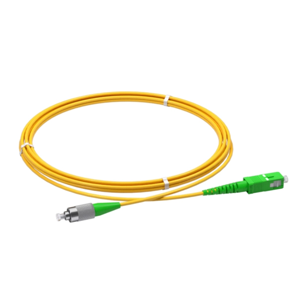
What type of connector is typically used for fiber optic pigtails
Fiber optic pigtails are equipped with a single pre-terminated connector at one end, while the other end consists of bare fibers. Unlike a patch cord—which has connectors on both ends—the bare fiber end of a pigtail is designed to be permanently spliced (either by fusion or. In such contemporary fiber optic communication systems, low-loss, and connectivities, which have reliability, are crucial for not only maintaining high-speed but also high-quality data transmission. Compared with quick termination or epoxy and polish connections placed on the field. These factory-terminated, single-connector optical fiber assemblies are the gold standard for creating clean, reliable, low-loss splices in termination boxes, splice closures, optical distribution frames (ODF), and FTTx infrastructure. As a commonly used network connection device in fiber optic networks.
[PDF Version]
-
How to separate the fiber cores of OPGW24-core optical cable
Removing the aluminum strands and outer layers of the OPGW cable exposes the fiber optic cores 7, which is essential for proper termination. Use a file to smooth any sharp edges after removing the aluminum strands 8. Carefully separate the metal loose tubes without damaging. Proper termination of OPGW cables involves precise steps like careful handling 3, removing outer layers, cleaning fibers, and securing with clamps. In the construction of electric power dedicated communication network, the number of optical fibers used is usually 12 to 24 cores. With the continuous expansion of system capacity according to new business requirements, the number of cores is gradually increasing, and individual line sections have. out this step, cut a small piece of pipe, about 2 feet, from the free end of the cable and practice cuttin of the cable. While holding the cable, pull the optical units completely out of the pipe by pullin toward the tower. What is Fiber Optic Splicing and Why is it Needed? – #1. First, a heat-shrink tube is placed over the OPGW cable.
[PDF Version]
Telecom Racks & Cabinets
19-inch racks, wall-mount cabinets, open frames with high load capacity and seismic rating.
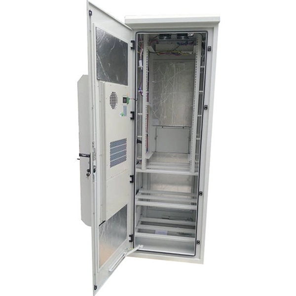
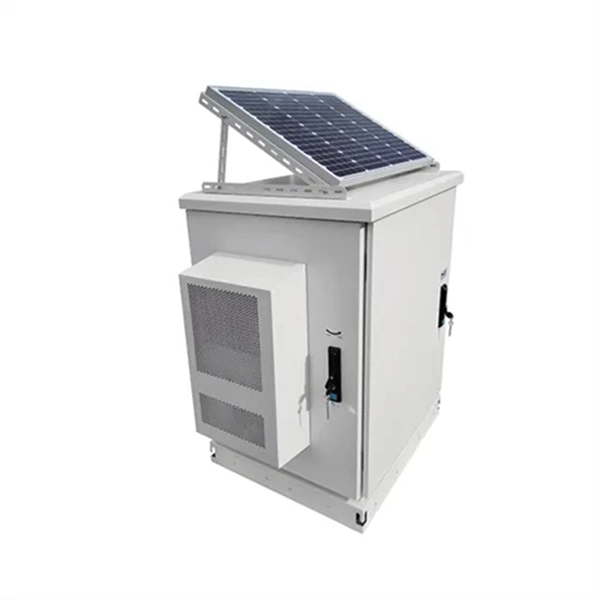
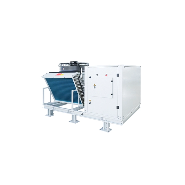
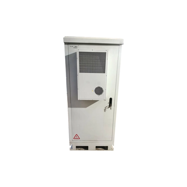
Outdoor Climate Cabinets
IP55/IP66 outdoor enclosures with integrated cooling/heating, -40°C to +55°C operation.
Smart PDUs & Power Distribution
Intelligent PDUs with remote monitoring, per-outlet switching, and environmental sensors.
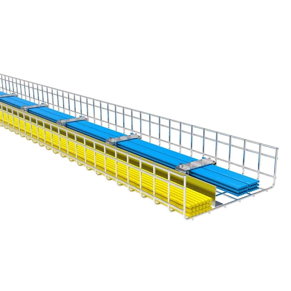
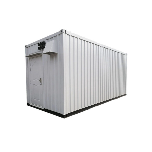
Shelters & Network Cabinets
Prefabricated telecom shelters, emergency comms shelters, and network cabinets with cable management.