-
What types of ports are there for single-mode fiber optic cables
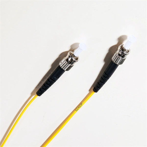
Most SFP fiber optic modules use LC connectors, while SC connectors are mainly found in legacy networks and MPO/MTP connectors are used for high-density cabling rather than directly on standard SFP modules. The fiber connector types, sometimes referred to as terminations, link fiber optic cables together through terminals, switches, adapters, and patch panels, by bridging the gap between their internal glass fibers that transmit the data down the length of the cable. That is why I am writing this guide. I have gathered information from all over to assist you in understanding everything about them. After reading this guide, you will understand the. There are different fiber optic connectors types, including LC/SC/ST/FC/MU/DIN fiber connectors, Rosenberger Q-RMC/NEX10 connectors and more. Key features include: LC connectors are compact and highly efficient, making them a popular choice for telecom and enterprise networks.
[PDF Version]
-
How to connect fiber optic ports and network ports to the panel
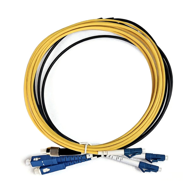
This comprehensive guide will explore the importance and benefits of this integration, provide an understanding of fiber optic cable and Ethernet ports, discuss their compatibility, and offer a step-by-step process for connecting them. Fiber optic patch panels are mostly mounted in 19 inch relay racks, but they can also be mounted on freestanding rails, in cabinets and also on walls. Future plans for change will be discussed, as well as the bandwidth required. The design's intent is to minimize future errors due to snags, awkward cable access, slack, and unprotected. Here's a step-by-step guide to help you properly arrange fiber optic patch panels in a data center environment. Before installation, assess your network's current and future needs: Use this information to select the appropriate patch panel type—rack-mounted, wall-mounted, or modular high-density. Fiber optic cabling is increasingly used to connect network switches and other datacom equipment, especially in long-distance and mission-critical applications. These are one side pre-terminated pieces of fiber. 12 colors LC/APC Fiber Pigtail with Single mode I went with G.
[PDF Version]
-
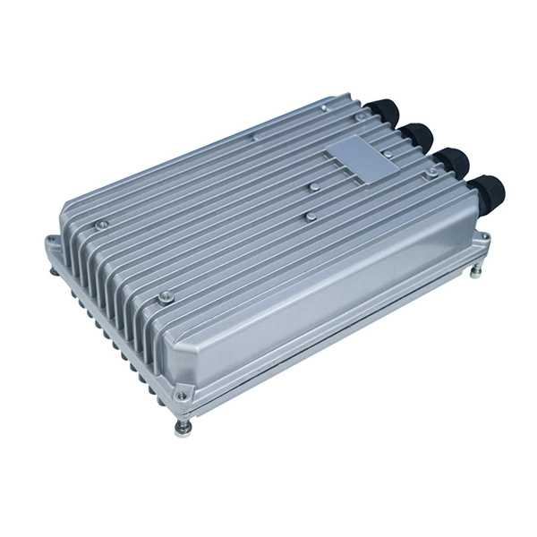
Do Huawei switches have fiber optic ports How do I connect them
The DB50 port on the rear panel of the switch is connected to the DB50 port on the panel of the fiber management tray panel through a DB50 jumper power cord. They can function as core, aggregation, and access devices on campus networks and connect to upstream and downstream devices. Optical modules are widely used in switches, network interface cards (NICs), routers, and other communication devices. During use, reading optical module information helps understand its real-time operating status, enabling faster troubleshooting of link abnormalities. Solution: To solve this problem, you can follow these steps: Check if the fiber and optical modules are compatible. Perform a. All-optical Ethernet switches are a type of switch that provides optical uplink and downlink ports, making them an ideal choice for building an all-optical campus network. You can also use the Hardware Center to query the.
[PDF Version]
-
Finland Cost Fiber Optic Enterprise Router SFP
The table below compares typical optics you will encounter when choosing a WAN fiber module for SFP router WAN interfaces. Always treat these as reference classes; exact reach depends on the transceiver's optical budget and your actual fiber loss. SFP optics are commonly used for 1G, 2. Your selection should be validated against IEEE link behavior and vendor datasheets, not just vendor marketing labels. Routers negotiate link based on the electrical SerDes rate and the optical. SuomiCom's fiber optic internet is an excellent choice for your business if you seek the highest quality and fastest connection. Our highly fault-tolerant network is built with our customers' needs in mind and is implemented with Nokia equipment in critical parts. It can be used to build secure, reliable, ultra-high bandwidth, and ultra-high concurrency all-optical Wi-Fi networks for SMEs.
[PDF Version]
-
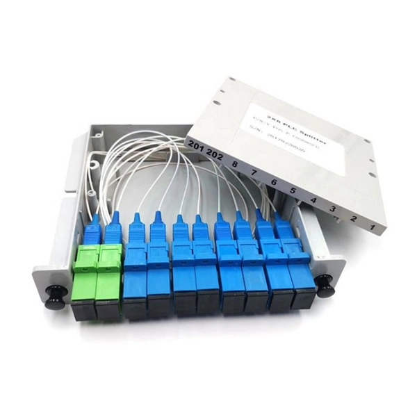
How many ports does the optical fiber splitter distributor have
Featuring 24 fiber ports, comprising 3 inlet, 16 outlets, this fiber optic splitter box ensures seamless connectivity across your fiber optic infrastructure. Cost Efficiency: A single OLT port can serve 8–64 ONTs via a splitter, reducing the number of OLTs, fibers, and deployment labor needed. Passive Operation: Splitters have no active electronics, so they require no power, cooling, or maintenance—lowering operational costs (OPEX) for ISPs. Indoor/Outdoor Wall Mounted, Single Door Fiber Distribution box is ideal for end terminations of fiber optic runs in residential or commercial buildings. Integral gasket seal provides IP65 level of protection. Pre-installed with 24 SC/APC simplex couplers and two 1x8 terminated SC/APC splitters, it effortlessly supports single-mode fiber optic. A fiber broadband provider typically determines and overall split ratio for the network, such as 1x32 or 1x64, and uses combinations of splitters to meet that ratio with each PON port. 1x32 splits were common in North America for G-PON architectures.
[PDF Version]
-

How to calculate the number of ports on a fiber optic patch panel
The fundamental calculation formula is: Total patch cords = Total number of device ports × Connection factor Where the connection factor depends on the connection method: 2. Scenario-Based Calculations The redundancy factor is typically 0 (no redundancy) or 1 (1:1 redundancy). Premium-Line 19” Rack mountable fiber optic patch panel is designed for both patching and splicing, accepts whole range of adapters including SC, ST, FC, LC adapters. 2 * Rear cable entries accommodate cables with diameter below 10mm. These options cater to different network requirements and capacities. Network architects and procurement managers must now evaluate patch panels not merely. Follow TIA-942 or ISO/IEC 11801 standards for structured cabling. It is important to know the.
[PDF Version]
-
Can fiber optic cables be connected to switch ports
Choose an SFP module based on the fiber optic cabling that will be connected to the network switches. Most modern fiber-enabled network switches require an SFP transceiver module. In addition, fiber cables can transmit data over several kilometers without signal degradation, making them ideal for connecting switches in large campus networks and between different buildings. As they do not emit electromagnetic signals, they're difficult to tap and secure against eavesdropping. The 10/100/1000 Ethernet ports on the switches use RJ-45 connectors. The choice between SFP and SFP+ depends on the network speed requirements, with SFP+ supporting higher speeds (up to 10 Gbps). As data rates increase from 10G → 100G → 400G → 800G, patch cables must handle more bandwidth, more density, and stricter.
[PDF Version]
-
Does the network panel have dual ports with fiber optic cable
The FTWM2 mini wall mount fiber patch panel can support up to 2 optical fibers with both SC and SC APC duplex adapter types supported. With its compact size, it can be deployed at locations where. The Cisco ® solution of panel and cable assemblies offers versatile solution for any breakout from 4x10 Gbs to 400 Gbs native. The panels are compatible for Top of Rack (ToR), Middle of Rack (MoR), and End of Row (EoR) layouts. Patch Panel Cisco simplifies optical connectivity management. The Cable Matters 6-Port LC OM1/OM2/OM3/OM4 Multimode Fiber Optic Patch Panel future-proofs your fiber optic network expansion.
[PDF Version]
-
Lifespan Comparison of Angolan Fiber Optic Enterprise Routers SFP
This article helps network engineers and field techs choosing SFP transceivers for enterprise edge deployments: how to match wavelength, reach, power class, connector type, and DOM behavior to the router and the handoff fiber. Since the dawn of the internet in the early 1990s, internet speeds have increased by over 1,000 times and there is no end in sight to this growth. I will also cover the operational details I have used on site, including. This guide provides a clear, practical comparison among the most common transceiver types - GBIC, SFP, XFP, and SFP+ - to help you make informed procurement decisions. com, we specialize in Cisco-compatible and NS Comm transceivers, offering enterprise customers tested, certified. Real Lifespan, What Wears Them Out, and Practical Replacement Advice If you ask three engineers how long an SFP or QSFP should last you'll get five answers, and that's because datasheet MTBF numbers don't tell the whole story. Thus, understanding the full lifecycle of fiber optic cables is essential not only for.
[PDF Version]
-
How to configure the number of ports on a fiber optic patch panel
Here's a step-by-step guide to help you properly arrange fiber optic patch panels in a data center environment. Before installation, assess your network's current and future needs: Use this information to select the appropriate patch panel type—rack-mounted, wall-mounted, or modular high-density. Fiber patch panels come in various configurations, including 12-port, 24-port, 48-port, 72-port, 96-port, and 144-port fiber distribution frames. These options cater to different network requirements and capacities. The most common configurations are 24 port fiber patch panel and 48 port fiber. ● The patch panel is a long-term solution that can provide high-density port connectivity solutions for 4x10 Gbps, 100 Gbps, 2x100 Gbps, 4x100 Gbps, 400 Gbps, 2x400 Gbps, and 4x400 Gbps breakout requirements. And label the ports to identify different cables so that technicians have clear instructions on what they need. Suitable to SC LC FC ST or other fiber connectors as requested, Meanwhile, 12, 24, 36, 48, 72, 96, 144 ports are available Mounted directly onto walls for space-saving installations.
[PDF Version]
-
Block Diagram of a Digital Fiber Optic Communication System
TL;DR: A fiber optic communication block diagram visually breaks down how data travels through fiber optic cables—from signal generation to transmission, amplification, and reception. In this lecture, we are going to learn about Optical fiber communication, a Block diagram of optical fiber communication systems, types, and modes of optical fiber, and the advantages and applications of optical fiber communication. RECONSTRUCTION OF TEACHER EDUCATION IN SOMALIA: The Case of Garowe Teacher Ed. by Cambridge Early Learning Centre. There are mainly two types of optic cables are used - 1. Multi-Mode Optical Fiber Cable 2.
[PDF Version]
-
Can a router use fiber optic cable instead of a network cable
Q: Can I plug a fiber optic cable directly into a router? A: Only if your router has an SFP port designed for fiber. The process to connect fiber optic cable to router requires careful attention to detail, but I'll walk you through every critical step with the precision and clarity you deserve. This comprehensive guide combines industry standards with field-tested practices to ensure you achieve a rock-solid. There is no such thing as the “best” routers or Wi-Fi systems for a particular Internet service provider or type—Fiber-optic, Cable, or whatever. Any standard router, including the primary unit of a mesh Wi-Fi system, will work at its full potential with any standard Internet broadband terminal. Setting up a fiber internet connection requires understanding key hardware components and following a specific connection sequence to establish your home network. However, modern networks often combine both technologies.
[PDF Version]
-
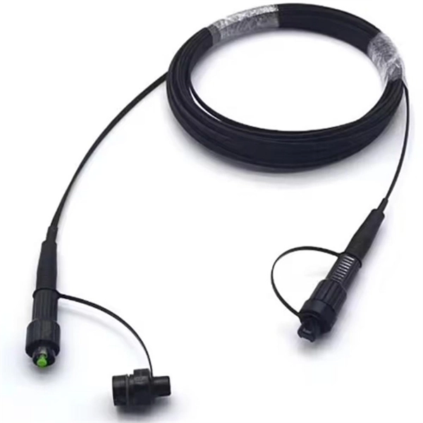
How to separate the fiber cores of OPGW24-core optical cable
Removing the aluminum strands and outer layers of the OPGW cable exposes the fiber optic cores 7, which is essential for proper termination. Use a file to smooth any sharp edges after removing the aluminum strands 8. Carefully separate the metal loose tubes without damaging. Proper termination of OPGW cables involves precise steps like careful handling 3, removing outer layers, cleaning fibers, and securing with clamps. In the construction of electric power dedicated communication network, the number of optical fibers used is usually 12 to 24 cores. With the continuous expansion of system capacity according to new business requirements, the number of cores is gradually increasing, and individual line sections have. out this step, cut a small piece of pipe, about 2 feet, from the free end of the cable and practice cuttin of the cable. While holding the cable, pull the optical units completely out of the pipe by pullin toward the tower. What is Fiber Optic Splicing and Why is it Needed? – #1. First, a heat-shrink tube is placed over the OPGW cable.
[PDF Version]
-
How to install fiber optic cables using a fiber optic patch panel
This article provides a comprehensive guide on installing fiber optic patch panels, integrating practical installation steps with insights from business intelligence and data analytics. Network administrators can neatly organize and label fiber optic cables using a patch panel, making it easier to identify and manage specific connections. This improves overall network reliability and makes future modifications or expansions easier. Fibre Optic Patch Panel Installation Fibre Optic Cabling Know How - how to connect Fibre Optic Cable to a Patch Panel This video shows you how to install the. Fiber optic patch panels are now gradually becoming a common product in optical fiber wiring systems, especially in high-density wiring environments such as data centers and server rooms. Here is a step-by-step guide on how to install a fiber optic patch panel.
[PDF Version]
-
How long should the fiber optic cable splice box be
The proper length of fiber is needed to allow splicing and then neatly storing fiber in the splice tray. Inside splice closures and at each end, cables with metallic shielding or strength members must be properly grounded and bonded. Clean the loose tube and the reinforced core sheath with a cleaning agent, remove the excess filling tube, and polish the cable sheath 150mm long with the. Installing a fiber optic splice closure efficiently and effectively requires attention to detail and adherence to specific procedures. Here's a structured guide to ensure optimal installation, protecting the integrity of your fiber optic network connections. They protect the cable splices from physical damage, moisture, and other environmental factors.
[PDF Version]
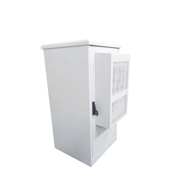
Telecom Racks & Cabinets
19-inch racks, wall-mount cabinets, open frames with high load capacity and seismic rating.
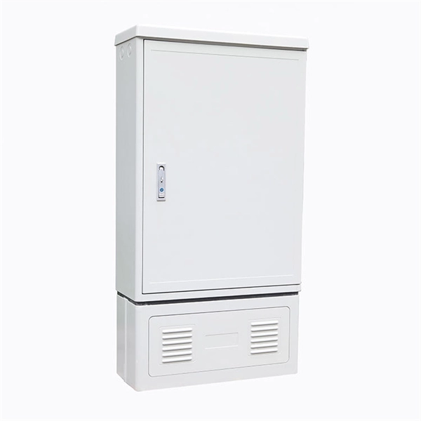
Outdoor Climate Cabinets
IP55/IP66 outdoor enclosures with integrated cooling/heating, -40°C to +55°C operation.
Smart PDUs & Power Distribution
Intelligent PDUs with remote monitoring, per-outlet switching, and environmental sensors.
Shelters & Network Cabinets
Prefabricated telecom shelters, emergency comms shelters, and network cabinets with cable management.