-
Applications of Optical Modules and Transceivers
Description: Explore how optical modules enable high-speed data conversion across data centers, 5G networks, storage systems, and WDM applications. From the fronthaul of base stations to the backhaul connecting core networks, optical transceivers are. In the world of fiber optic communications, optical transceiver modules play a pivotal role as interfaces that convert electrical signals to optical signals and vice versa. Learn about SFP, SFP28, CWDM, and DWDM solutions.
[PDF Version]
-
Price list for 200GLPO optical modules for data center interconnection
FS offers a growing portfolio of 200/400/800G optical transceiver modules and cables. Click to get your transceiver modules . Transceiver USA's TUSA200GQSFPFR4 optical modules are used in datacenter and enterprise networks. View price, stock and buy direct from Transceiver USA. The super-high density and backwards compatibility can enable high bandwidth and high speed links for data center and cloud networks. Offering flexible 2x100G or 1x200G configurations, our modules are perfectly compatible with major switch brands like Cisco, Arista, and Juniper - the core solution. The TQSFPDD-200G-SR8 is a Eight-Channel, Pluggable, Parallel, Fiber-Optic QSFP Double Density for 2x100 Gigabit Ethernet Applications.
[PDF Version]
-
What are the effects of high power consumption in optical modules
The high power consumption of optical modules not only increases operating costs but also limits the integration and sustainability of optical modules. Other external factors, such as operating temperature, network load fluctuations, cooling systems, and power management, can affect the performance and power consumption of optical modules. Reducing the power draw of thousands of transceivers directly translates to lower electricity bills. This article delves into the world of energy efficient fiber modules, examining their technical specifications, real-world. AI workloads, combined with other traffic, are putting immense pressure on networks — not just for bandwidth, but also for power and space, resources that don't scale linearly with data demand, given constraints in electrical supply, cooling and rack and aisle space. 5. As data rates continue to surge past 800G and into multi-terabit speeds, energy efficiency is becoming a critical concern for network operators, hyperscalers, and AI computing environments.
[PDF Version]
-
Interoperability between fiber optic transceivers and optical modules
Fiber module interoperability is the capacity of fiber optic transceivers—such as SFP, SFP+, QSFP, and CFP modules—to function reliably across different manufacturers' switches and hardware platforms without performance degradation or incompatibility issues. Fiber optic transceivers are indispensable devices in modern communication networks, used to convert electrical signals into optical signals and achieve long-distance transmission. However, in practical applications, the interoperability and compatibility issues of transceivers may directly affect. How to Ensure Interoperability Between Two Optical Transceivers? When it comes to the connection between two fiber optic transceivers, the following four factors should be taken into considerations: wavelength, speed, fiber type, and the connection to switches. In today's crowded OEM-compatible market, making the right choice is critical. This guide will help you understand how to ensure that the Fiber optical.
[PDF Version]
-
Can optical fibers and optical modules communicate
Q: Can optical modules be interconnected with fiber optic transceivers? The answer is yes. Operating at the physical layer of the OSI model, optical modules are core devices in optical. That is, metal medium communication represented by coaxial cables and network cables is gradually being replaced by optical fiber media. Composition of Optical Modules The optical module, known as Optical Transceiver in. This combination of this plus optical fiber (a high-performance transmission medium made of glass as thin as a human hair capable of trapping optical signals and transmitting them over long distances without significant attenuation) were game changers and set the stage for optical-based. Optical modules and fiber optic transceivers are both important devices in fiber optic communication systems, is there any difference between them? How to choose? This article will introduce the difference between the two and the precautions to be taken when connecting. Photonic systems are usually analyzed in terms of individual photons, although wave methods still.
[PDF Version]
-
Application of MCU Chips in Optical Modules
Optical modules must reliably report key parameters: temperature, supply voltage (Vcc), laser bias current, receiver (Rx) power, and transmitter (Tx) power. The MCU continually reads these analog metrics and interprets the module's operating condition in real time. Maxim Integrated's MAX32660 is ideal for today's optical module designs based on features and functions such as: The following figure is the internal block diagram of this MCU: Figure 1: MCU Internal Block Diagram. As shown from the block diagram and the previous description, the main advantages of. In optical transceiver modules—such as those in the LINK-PP SFP and QSFP family— Microcontroller Units (MCUs) act as the smart core, orchestrating essential monitoring, control, and diagnostics. This includes. Holtek has released a 32-bit Arm Cortex-M0+ Optical Module DDM MCUs, the HT32F52234 and HT32F52244. Small package size and low.
[PDF Version]
-
What are the optical modules of a switch
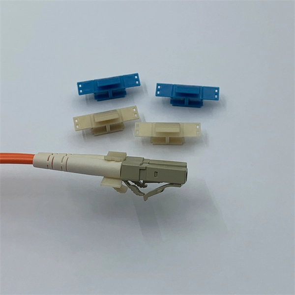
An optical module usually consists of an optical transmitting device (TOSA, including a laser), an optical receiving device (ROSA, including a photodetector), functional circuits,main control circuit board (PCBA), housing and optical (electrical) interface and other components. The optical module serves as a crucial component in optical fiber communication systems, operating at the physical layer, which is the lowest layer in the OSI model. Its primary function is to achieve optoelectronic conversion by converting electrical signals into optical signals and vice versa. Every time that light needs to change direction or jump.
[PDF Version]
-
Checking the status of optical modules on an H3C switch
Run the following command to view detailed interface and optical module status: show interface <interface-type> <interface-number>Run the following command to view detailed interface and optical module status: show interface <interface-type> <interface-number>Reading optical module information during use helps understand its real-time operating status, allowing you to locate the cause of link abnormalities more quickly. This document is not restricted to specific software or hardware versions. The value range varies with devices. backup: Specifies a file as a backup boot file. A main boot file is used to boot a device. General guidelines IMPORTANT: To prevent an issue from causing loss of configuration, save the configuration each time you finish configuring a feature. Category File name format Content following items: • Parameter settings in effect when an error occurs. dk / 20120724 # # Requires net-snmp-utils. # # changes by Gerrit Doornenbal: # 29-09-2016 added option check and usage-info # 08-03-2017 added IRF/PSU check based on mod.
[PDF Version]
-
Optical modules support single-mode and multi-mode operation
Single-mode fiber uses a 9/125 µm core/cladding structure that supports only one propagation mode, which minimizes modal dispersion and allows signals to travel tens of kilometers with low attenuation. Multimode fibers have larger cores (typically 50/125 µm or 62. 5/125 µm). Whether you're designing a short-range data center network or a long-distance metro backbone, understanding the distinctions between single vs. This guide breaks down these two critical dimensions of optical transceiver design to help. Choosing between Single Mode and Multimode Optical Modules will shape cost, reach and upgrade paths. A 1-core module uses a single fiber core for data transmission, while a 2-core module uses two cores. Understanding the differences between single-mode and multi-mode optical modules is crucial for selecting the right one for your specific network. Single-mode optical modules are usually applied to networks with long transmission distances and high transmission rates, such as the MAN passive optical fiber network, while multi-mode optical modules are usually applied to networks with short transmissi With the rapid development of data centers.
[PDF Version]
-
Do optical modules need to be the same model
Optical modules come in various types, and their external structures are not exactly the same. However, their basic compositional structure includes the following parts, as shown in Figure 1-2, which illustrates the external structure of an optical module (using the SFP. The optical module serves as a crucial component in optical fiber communication systems, operating at the physical layer, which is the lowest layer in the OSI model. Its primary function is to achieve optoelectronic conversion by converting electrical signals into optical signals and vice versa. Among various optical module form factors, SFP (Small Form-Factor Pluggable). An optical module is mainly composed of optoelectronic devices (including the optical transmitter and optical receiver), functional circuitry, and optical interfaces. Transceiver compatibility is a key concern in enterprise network deployments.
[PDF Version]
-
How to calculate the transmission speed of a 4-core optical fiber cable
This calculator determines the bits per second that can be transmitted through a multimode fiber cable, given its bandwidth. Key Parameters: • Center Diameter, Fiber Diameter, Packing Efficiency, Section Count Calculation: Visualization: • Color-coded radial diagram with per-section. RP Fiber Calculator is a highly convenient software for doing various calculations on optical fibers with radially symmetric refractive index profiles. It has an intuitive graphical user interface with tabs for the following purposes: Your browser does not support the video tag. The configuration and results can be exported as PDF. You can also select components to configure connections below and add the field configuration below it. The components will show. A 500 MHz·km fiber can transmit 500 MHz optical signals over 1 kilometer, or 250 MHz over 2 kilometers, demonstrating the inverse relationship between bandwidth and distance. 792 meters per microsecond (µs) or 3.
[PDF Version]
-
Requirements for Data Optical Cable Splicing
(1) This section describes approved methods for splicing plastic insulated copper and fiber optic cables. Typical applications of these methods include aerial, buried, and underground splices. Fiber optic splicing is the process of joining two optical fibers end-to-end. (2) American National Standard Institute/National Fire Protection Association (ANSI/NFPA) 70, 1993. The Network Installers engineers and installs commercial fiber optic cabling for businesses and government agencies across the United States. (FOA) was founded in 1995 to help develop the workforce to build the fiber optic networks to support a rapid expansion in communications and the Internet. fCONSTRUCTION QUALITY REQUIREMENTS FOR FTTP & SSP Work Orders This document provides Construction Technicians, Construction Managers, FTTP/SSP Vendors, and Inspectors with the essential information to ensure a quality build and to successfully pass an Outside Plant Inspection.
[PDF Version]
-
Myanmar Imported Data Center Cold Aisle High Density
This study analyzes the IT environment of the hot aisle containment (HAC) system, which has been considered an essential solution for high-density data centers. The thermal performance was analyzed for an IT server room with HAC in a reference data center. Hot Aisle Containment (HAC): hot exhaust and sends back to Aircons Water is 4times more heat-absorbent and 24 times more heat-conductive than air. Direct-to-Chip (Cold Plates):. At Energy Solutions Intelligence, we analyze operational data from hyperscale operators, colocation providers, and enterprise deployments to benchmark liquid immersion cooling economics against advanced air-cooling architectures across power densities from 15 kW/rack to 100+ kW/rack. Both approaches remain essential since most high-density environments still mix. Hot aisle and cold aisle containment are foundational concepts in data center design. When implemented correctly, they improve efficiency, reduce energy consumption, extend equipment life, and enhance overall reliability. It can also resolve hot spots in traditional.
[PDF Version]
-
How many meters high can a communication optical cable be used
Fiber optic cable can be run anywhere from 300 meters up to 80 kilometers (roughly 50 miles) depending on the cable type, transceiver used, and network standard. One type of single mode fiber is known as “G. 652,” which is commonly used in telecommunications networks. Receiver Sensitivity Higher receiver sensitivity means that it can detect weaker optical signals. Even if the optical signal. Fiber optic cables have revolutionized modern communication networks by enabling blazing-fast data transmission across vast distances.
[PDF Version]
-
Delivery date in Sweden for LPO optical modules SFP
(SZSE: 300502) used OFC 2023 to launch 800G linear-drive pluggable optical transceivers (LPOs). The use of a linear drive design removes the need for DSPs and CDRs, thus reducing power consumption and latency, the company asserts. Next-generation 400G and 800G modules for data centers, AI clusters, and telecoms — validated in a European lab, ready to ship from Europe. What is Low-Power Optical Transceivers (LPO)? Linear Pluggable Optics (LPO) replace the DSP inside the optical module with linear analog components, shifting. CHENGDU, China and SAN DIEGO, March 22, 2024 /PRNewswire/ -- Eoptolink Technology Inc. The idea is simple: instead of a DSP (digital signal processor) inside the module – replacing it with transimpedance amplifier (TIA) and a driver chip with high linearity and EQ capability – LPO shifts signal processing into. New Castle, Delaware – FS, a trusted provider of ICT products and solutions, has launched its cutting-edge 800G Linear Pluggable Optics (LPO) module.
[PDF Version]
Telecom Racks & Cabinets
19-inch racks, wall-mount cabinets, open frames with high load capacity and seismic rating.
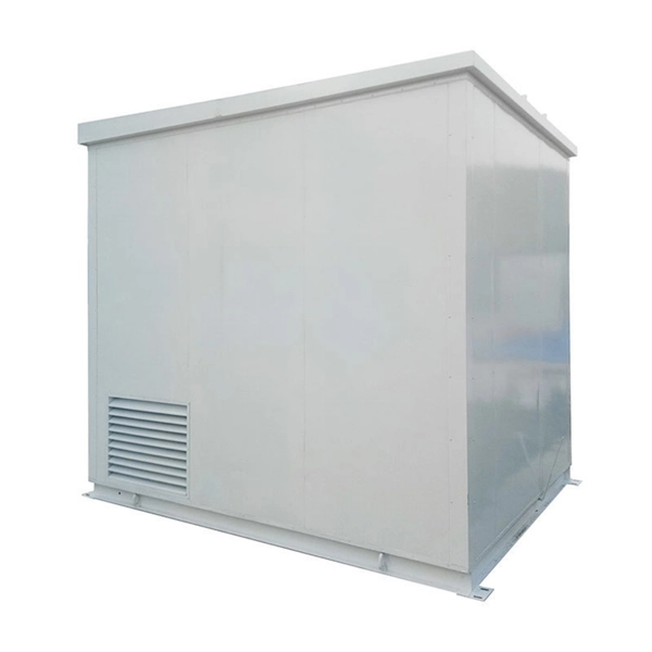
Outdoor Climate Cabinets
IP55/IP66 outdoor enclosures with integrated cooling/heating, -40°C to +55°C operation.
Smart PDUs & Power Distribution
Intelligent PDUs with remote monitoring, per-outlet switching, and environmental sensors.
Shelters & Network Cabinets
Prefabricated telecom shelters, emergency comms shelters, and network cabinets with cable management.