FOC Splicing and Testing Method Statement | PDF | Optical Fiber
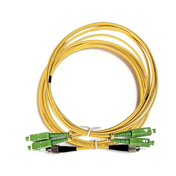
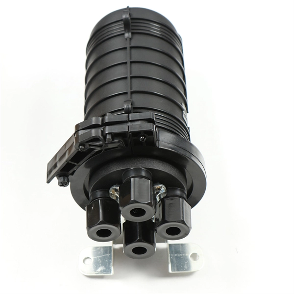
Splicing of all fibre optic cables shall be carried out by means of a fusion-splicing machine and optical fibre cleaver. Both the cables that have to be jointed will be prepared and splicing shall be carried out
7. Splice Measurement and Characterization
In this chapter we review technologies for measuring the optical qual-ity of a fusion splice. Since the optical transmission loss of a fusion splice is almost always its most important performance
The FOA Reference For Fiber Optics
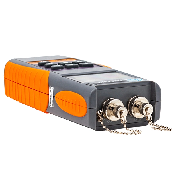
It can verify splice loss, measure length and find faults. The OTDR is also commonly used to create a "picture" of fiber optic cable when it is newly installed. Later, comparisons can be made between the
Splicing, Testing, and Troubleshooting OPGW and ADSS Fiber
This paper will provide a brief overview of the history of fiber-optic communications and types of fibers, and discuss handling, splicing, testing and troubleshooting of fiber-optic cables. In addition, it will
Application Note_Splicing & OTDR Measurements
This Application Note explains all aspects of fusion splicing on Draka single-mode products, ESMF and BendBright-XS. This includes the testing of spliced fibers.
FOC Splicing and Testing Method Statement | PDF
Splicing of all fibre optic cables shall be carried out by means of a
ITU-T Rec. L.400/L.12 (02/2022) Optical fibre splices
In practice, the in-field measurement of each splice loss during the construction of a fibre link is usually estimated by the fusion splicing machine (when loss estimation is a facility) or by a one-way optical
Is That Splice Really Good Enough? Improving Fiber Optic Splice
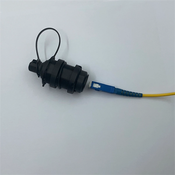
For product splicing of pig-tailed components, actual splice loss measurement is usually not possible since the free ends of the fiber are not accessible for connection to a source and detector.
7 CFR 1755.404 -
(1) Tests and measurements shall be made to ensure that the armor of fiber optic cables is continuous. There are two areas of concern. The first is armor bonding within a splice and the second is armor
Fiber Optic Testing Standards
The Contractor tasked to perform testing or splicing on any fiber optic cable will follow these testing standards to fulfill their contractual obligations. The Contractor must utilize the correct equipment and
Guidelines Corning Recommended Fiber Optic Test
Corning Optical Communications reserves the right to improve, enhance, and modify the features and specifications of Corning Optical Communications products without prior notification.
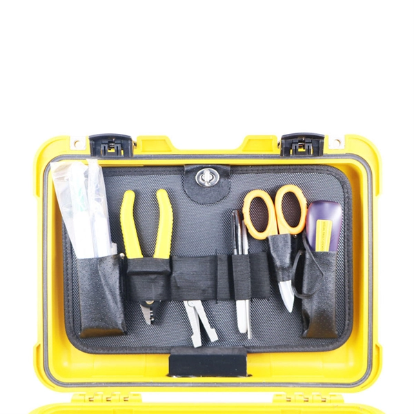
Fiber Optic Fusion Splicing Guide: From Safety to Troubleshooting
Learn Fiber Optic Fusion Splicing: step-by-step guide to safe, precise fiber prep, fusion, and testing for low-loss, high-quality splices in optic networks.
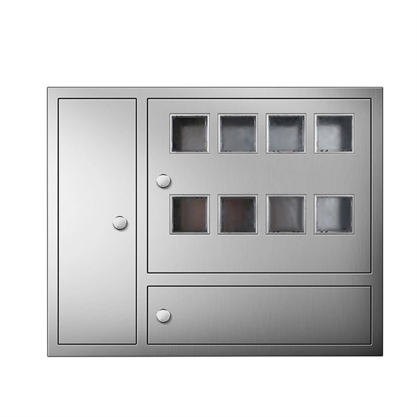
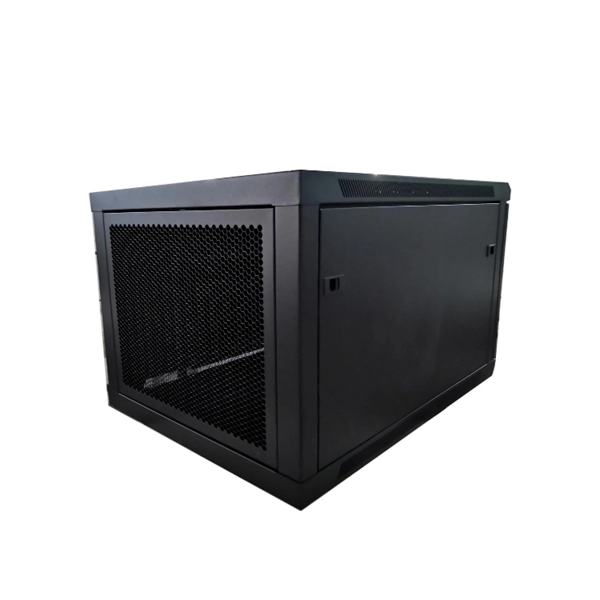
Telecom Racks & Cabinets
19-inch racks, wall-mount cabinets, open frames with high load capacity and seismic rating.
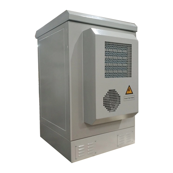
Outdoor Climate Cabinets
IP55/IP66 outdoor enclosures with integrated cooling/heating, -40°C to +55°C operation.
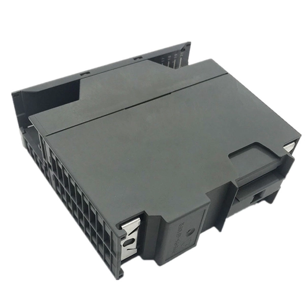
Smart PDUs & Power Distribution
Intelligent PDUs with remote monitoring, per-outlet switching, and environmental sensors.
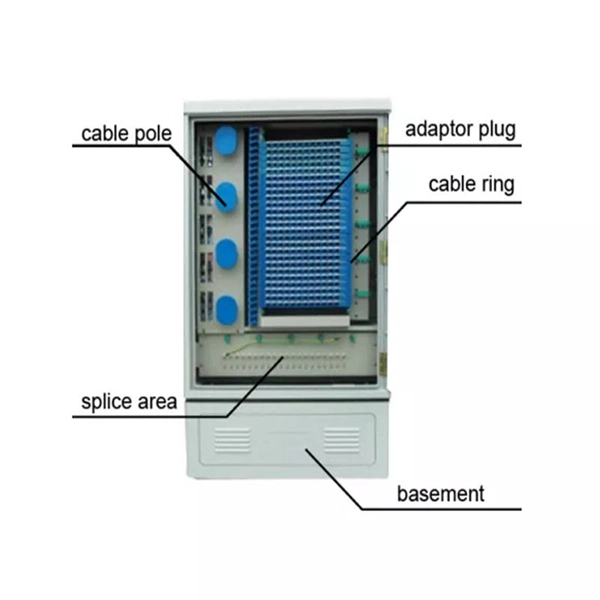
Shelters & Network Cabinets
Prefabricated telecom shelters, emergency comms shelters, and network cabinets with cable management.