The Complete Step-by-Step Guide to Fiber Optic Splicing
In this guide, we cover the basics of fiber optic splicing, how to perform splicing using two different methods, and finally some best practices to perform good fiber splicing.
Fiber Optic Testing: Understanding Key OTDR Event
Learn more about the key event types that are identified by an OTDR, one of the most important devices for testing and troubleshooting optical fibers.
Issues Concerning Dissimilar Single Mode Fiber Splicing
In splices of dissimilar single mode fibers, there is frequently a vertical shadow or line at the splice point which is visible in the spliced fiber image on the LCD screen of the fusion splicer.
The FOA Reference For Fiber Optics
Splitting all those fibers out to splice individually would be time consuming, so ribbon fusion splicers, also called mass fusion splicers, can splice entire ribbons at one time, creating a splice that looks like this.
Fiber Optic Cable Splice: The Complete Guide
This guide explores everything about fiber optic cable splice —from fiber fusion splice basics to how to splice fiber cable step-by-step—covering tools, techniques, and practical tips.
Fiber Optic Cable Splicing Explained
Mechanical splicing uses a small, mechanical splice, about 6cm long and 1cm in diameter that permanently joins the two optical fibers. This precisely aligns two bare fibers and then secures
ANSI/TIA-568.3-E: Optical Fiber Cabling and Components Standard
The TIA FOTC provides an overview of the ANSI/TIA-568-3.E Optical Fiber Cabling and Components Standard.
Fiber Optic Fusion Splicing Guide: From Safety to Troubleshooting
Learn Fiber Optic Fusion Splicing: step-by-step guide to safe, precise fiber prep, fusion, and testing for low-loss, high-quality splices in optic networks.
ITU-T Rec. L.400/L.12 (02/2022) Optical fibre splices
When different types of fibres are spliced together, e.g., G.652.D and G.654.E, a distinct vertical line shows up at the position of a splice point, as indicated in Figure III.3-b.
Everything you need to know about fiber optic termination
Connector and splice loss is caused by a number of factors. Loss is minimized when the two fiber cores are identical and perfectly aligned, the connectors or splices are properly finished and no dirt is present.
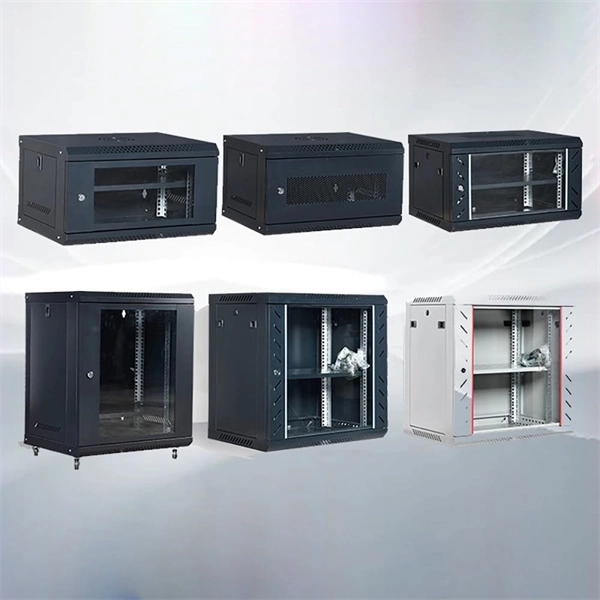
Telecom Racks & Cabinets
19-inch racks, wall-mount cabinets, open frames with high load capacity and seismic rating.
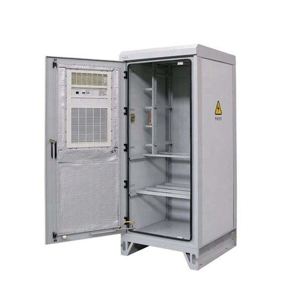
Outdoor Climate Cabinets
IP55/IP66 outdoor enclosures with integrated cooling/heating, -40°C to +55°C operation.
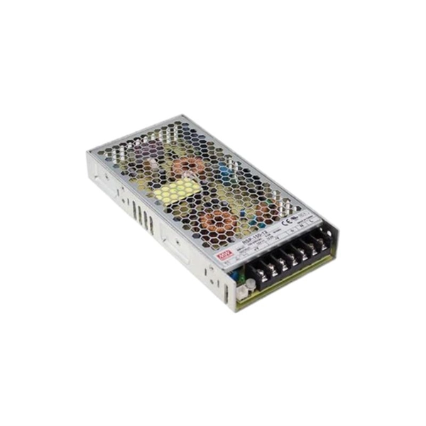
Smart PDUs & Power Distribution
Intelligent PDUs with remote monitoring, per-outlet switching, and environmental sensors.
Shelters & Network Cabinets
Prefabricated telecom shelters, emergency comms shelters, and network cabinets with cable management.