CABLE TRAY SYSTEMS GUIDE
Commonly called the Load Class, this defines the load-carrying capability of the tray for a specific support span distance. The design and cost of the cable tray is greatly affected by this designation.
An In-depth Analysis for Optimal Cable Tray Support Span
This study presents not only material and geometry frequently used for cable tray but also the formula to estimate the maximum cable load which can be
How to Calculate the Cable Tray Support Quantity
Learn how to accurately calculate cable tray support quantities in electrical installation projects. Our guide covers methods, tools, and practical examples for effective cable tray support
Cable Tray Technical Guide A practical guide to product selection
SOLID-BOTTOM CABLE TRAY Providing additional cable protection, solid-bottom cable tray is sometimes preferred to support and protect numerous small instrumentation and control cables.
A Guide to Installing and Supporting Electrical Cable Trays
This guide covers the critical steps, from selecting the right electrical cable tray and performing accurate cable fill calculations to managing a safe cable pull through and ensuring all bonding and grounding
IEC 61537 Cable Support Systems Guide
The document discusses cable support systems used internationally. It provides information on calculating cable loads using cable weight tables to determine the maximum load a cable tray can
NEC Article 392 Guide: Ensuring Compliance for Cable Tray Systems
Normal Spans: These trays must have support after every 2 or 3 meters. This will involve purchasing additional hangers and wasting more time drilling holes in the ceiling.
GUIDE CABLE TRAYS TECHNICAL
In accordance with its continuous impro-vement policy, Legrand reserves the right to change the specifications and illus-trations without notice. All illustrations, descriptions and technical information
B-Line series Cable Tray Design Considerations
Our wind certification report provides you with list of acceptable B-Line series cable tray supports, fittings and covers based off of the environmental conditions, cable loading, and type of cable tray in your
Supporting MC cable with Cable Tray | Page 2 | Information by
In Canada, the CEC rule 12-2200 details the requirements. With cables less then 50mm in diameter in a tray, the minimum vertical clearance is 150mm between trays. With cables greater then
Guide to cable support systems
The load capacity of the cable trays according to the support width can be read off in the diagram using load curves – here, shown as an example for a cable tray with the tray widths 100 to 600 mm.
Telecom Racks & Cabinets
19-inch racks, wall-mount cabinets, open frames with high load capacity and seismic rating.
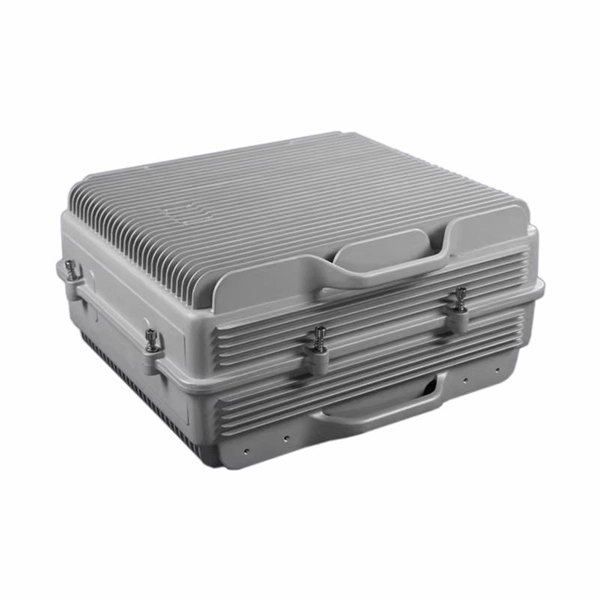
Outdoor Climate Cabinets
IP55/IP66 outdoor enclosures with integrated cooling/heating, -40°C to +55°C operation.
Smart PDUs & Power Distribution
Intelligent PDUs with remote monitoring, per-outlet switching, and environmental sensors.
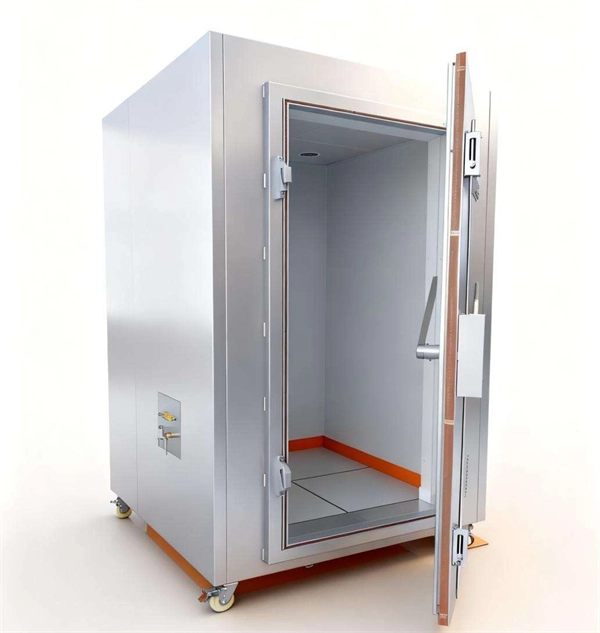
Shelters & Network Cabinets
Prefabricated telecom shelters, emergency comms shelters, and network cabinets with cable management.