Installation Guide
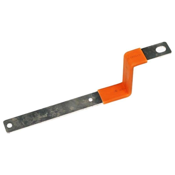
The ends of the tray fit into channels at the margins of the NoSplice support, then (supplied) Ground Splice is secured to the support. When utilizing the NoSplice, supports must be placed approximately

Instrumentation Cable Tray Installation Checklist and
Step-by-step instrumentation cable tray installation guide with safety tips, standards, inspections, and downloadable Excel checklist.
Cable Trays on Lower Decks in Public Passageways
Learn the essential measures for installing and maintaining cable trays on lower decks in public passageways or over roads to ensure safety and

CABLE TRAY INSTITUTE
The Cable Tray Institute has several standards and guidelines for the construction, testing, performance, and installation of cable tray. More information can be found here:
Technical Specification for Cable tray installation and cable laying
Approval of IPR shall be obtained for site preparation and marking the cable tray routes and locations of cable tray support before proceeding with the erection and installation work.
Cable Tray Installation Rules (NEC 392) – Electrical Trader
Core rules for selecting, installing, grounding, and filling cable trays—clearances, materials, separation, and bonding explained.

GUIDE CABLE TRAYS TECHNICAL
When fitting cable trays and their accessories, the products are cut on site to create changes of direction, adjust sections, etc. Damage can also occur during handling; as a result, both the
Cable tray manual
Cable tray may be installed as a support for Type MI cable in any location except where the cable is installed in a hoistway. Section 332-30 states that MI cable shall be securely supported at intervals
NEC Standards for Cable Trays: Grounding, Fill Capacity & Installation
This article provides a comprehensive framework that governs various aspects of cable tray installations, including the types of cables that are deemed acceptable for use, requirements for
NEC Standards for Cable Trays: Grounding, Fill Capacity
This article provides a comprehensive framework that governs various aspects of cable tray installations, including the types of cables that are deemed acceptable for use, requirements for
Cable Tray Installation
Once the cable is installed in an open cable tray installation, take care to protect the exposed cables from falling objects or debris that could cause damage to the cable. In areas where the cable tray
INSTALLATION GUIDE
Center hung tray supports allow for quicker and easier cable installation by allowing cables to be deposited into tray systems from each side. There is a maximum load capacity per hanger of 318 kg
Method Statement installation of Cable Trays and Ladders
This method statement covers the site installation of the cable tray & ladders and the requirements of checks to be carried out.
Cable Tray Installation Procedure Guide | PDF
It describes inspecting and storing cable trays upon receipt, installing trays flat or vertically, fixing trays to structures, designing trays to carry loads, providing
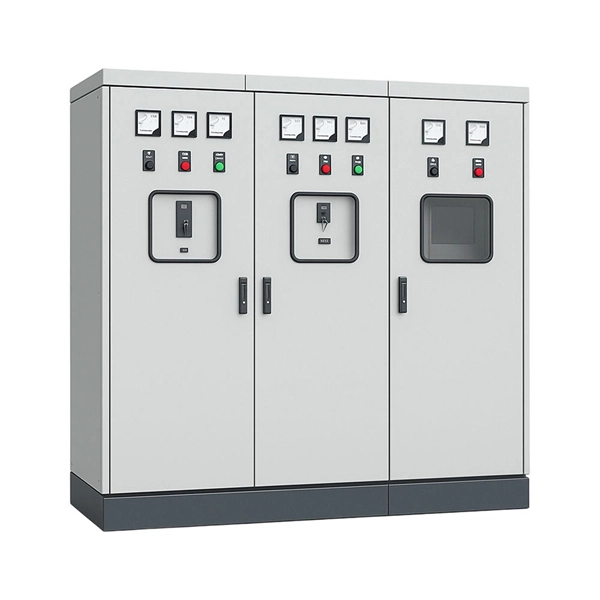
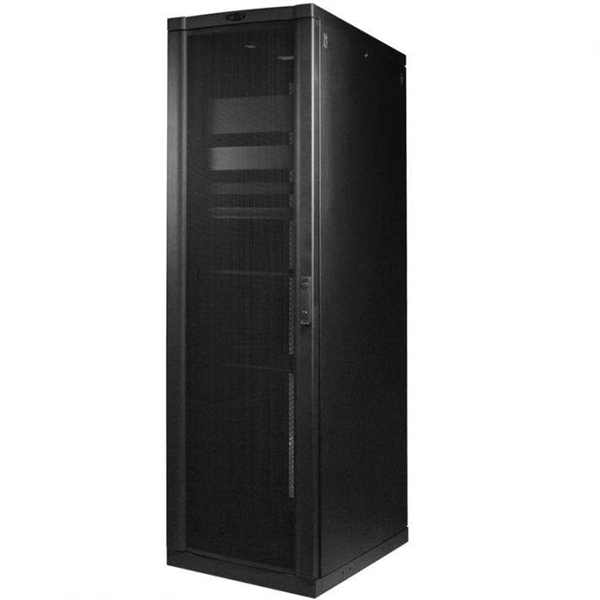
Telecom Racks & Cabinets
19-inch racks, wall-mount cabinets, open frames with high load capacity and seismic rating.
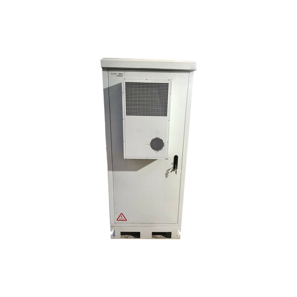
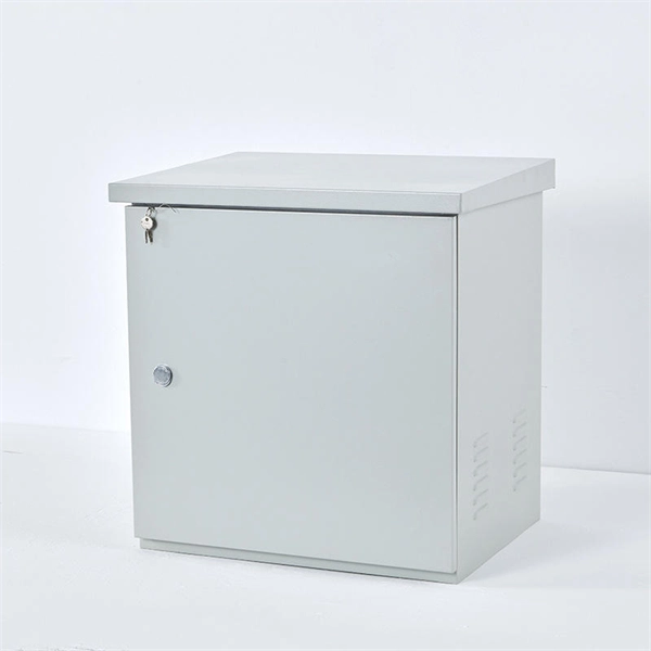
Outdoor Climate Cabinets
IP55/IP66 outdoor enclosures with integrated cooling/heating, -40°C to +55°C operation.
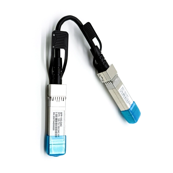
Smart PDUs & Power Distribution
Intelligent PDUs with remote monitoring, per-outlet switching, and environmental sensors.
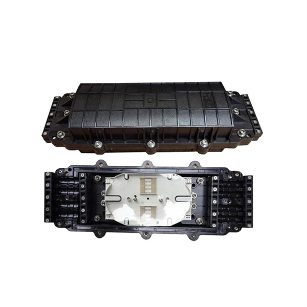
Shelters & Network Cabinets
Prefabricated telecom shelters, emergency comms shelters, and network cabinets with cable management.