How Does a Fiber Optic Splitter Work
This post provides a introduction to how does a fiber optic splitter work, and optical fiber splitter application in FTTH.
The Working Principle and Application Scenarios of
Explore the working principle of fiber optic splitters, their types, and real-world application scenarios in PON networks, FTTH, and more (1).
How Does a Fiber Optic Splitter Work
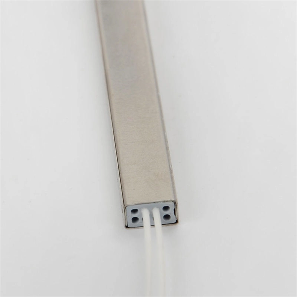
When an optical signal enters the splitter, it travels through the input port and propagates down the length of the waveguide. The waveguide then splits the light into two or more smaller

Knowledge of Optical Splitters
PLC splitter is based on planar light wave circuit technology. It consists of three layers: substrate, waveguide and cover. Waveguides play a key role in the splitting process that allows a
The Working Principle and Application Scenarios of Fiber Optic Splitters
Explore the working principle of fiber optic splitters, their types, and real-world application scenarios in PON networks, FTTH, and more (1).
Introduction to Passive Optical Network Splitter Architectures
Where splitters are placed in the network can make significant impacts on fiber counts, network cost and deployment time and operational steps, such as customer onboarding and maintenance.
Optical Splitters Demystified: The Silent Heroes Powering Your FTTH
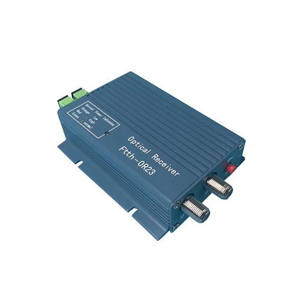
An optical splitter is a passive device, but it doesn''t work alone. It relies on active equipment at both ends of the fiber link: the Optical Line Terminal (OLT) at the provider''s central
Optical Splitters Demystified: The Silent Heroes
An optical splitter is a passive device, but it doesn''t work alone. It relies on active equipment at both ends of the fiber link: the Optical Line Terminal
How Does a PLC Splitter Work? An In-Depth Technical Guide
The step-by-step splitting process inside a PLC splitter is: Launching: The incoming optical signal from the input fiber is coupled to the input waveguide on the PLC chip. Propagation: The light
How does a Fiber Splitter work?
In summary, a Fiber Splitter operates by guiding and splitting light signals within an optical waveguide structure, utilizing the principles of total internal reflection and precise waveguide
Fiber Optic Splitter: How It Works & Types Guide
At its core, a fiber optic splitter relies on the principles of light reflection, refraction, and waveguiding to divide signals. Its design varies by type, but the underlying mechanism involves
Comprehensive Guide to Optical Splitters
In an optical splitter, the input optical signal is divided into multiple output optical signals, and the energy distribution ratio of each output optical signal is limited.
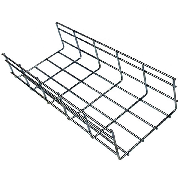
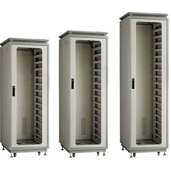
Telecom Racks & Cabinets
19-inch racks, wall-mount cabinets, open frames with high load capacity and seismic rating.
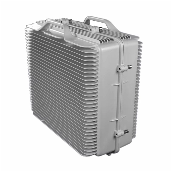
Outdoor Climate Cabinets
IP55/IP66 outdoor enclosures with integrated cooling/heating, -40°C to +55°C operation.
Smart PDUs & Power Distribution
Intelligent PDUs with remote monitoring, per-outlet switching, and environmental sensors.
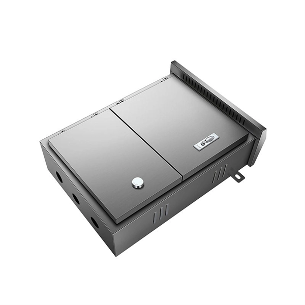
Shelters & Network Cabinets
Prefabricated telecom shelters, emergency comms shelters, and network cabinets with cable management.