Wiring and working principle of relay protection tester
Main circuit principle of relay protection test instrument The input AC220V power supply enters the input end of the double-brush voltage regulator T1 through the output control relay K1 through the
C37.110-2023
Abstract: The characteristics and classification of current transformers (CTs) used for protective relaying are described. This guide also describes the conditions that cause the CT output
CT Knee Point Voltage Requirements
This document discusses current transformer requirements for various protection applications in a MiCOM P544 or P546 relay. It recommends using class X or 5P current transformers and provides
applicationCT_accuracylimitfactorENa.fm
This document describes the calculation of the actual accuracy limit factor (Fa) for protection-type (P) current transformers (CT). First, the calculation of the actual burden of the CT, including connection
IEEE Guide for Protecting Power Transformers
The transformation ratio of the power transformer is considered and CT connections and ratios are selected such that the net current in the relay operating coil for any external fault is effectively zero,
Knee Point Voltage Calculator | Determine Transformer & Relay Voltage
Calculate the knee point voltage of current transformers (CTs) to ensure relay protection operates correctly. Ideal for engineers and electrical system designers.
Current Transformers for Protection Relays
Figure 1 shows an equivalent circuit for a current transformer. It includes an ideal transformer in which the primary is a single-turn winding connected to a current source.
IEEE Guide for Protective Relay Applications to Power Transformers
This guide deals primarily with the application of electrical relays and over-current protective devices to detect the fault current that results from an insulation failure.
MiCOM P544/P546 CT Requirements: Knee Point Voltage & K Factor
Detailed guide on CT requirements for MiCOM P544/P546 relays. Covers CT classes, knee point voltage, and K factor calculations for current differential and distance protection.
CT Sizing for Generator and Transformer Protective Relays
Modern relays often have algorithms that enhance the security of elements that are otherwise susceptible to current transformer (CT) saturation. In this paper, we consider some of the similarities
Transformer Protection Calculations & Settings
Transformer simulations show that magnetizing inrush current usually yields more than 30% of IF2/IF1 in the first cycle of the inrush so a setting of 15% usually provides a margin of security for older
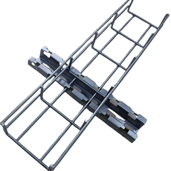
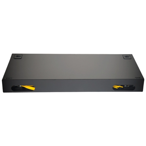
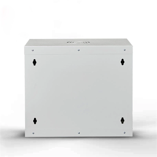
Telecom Racks & Cabinets
19-inch racks, wall-mount cabinets, open frames with high load capacity and seismic rating.
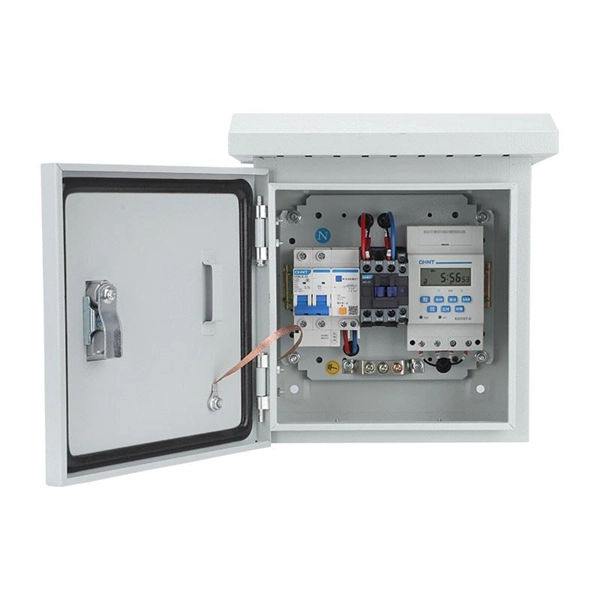
Outdoor Climate Cabinets
IP55/IP66 outdoor enclosures with integrated cooling/heating, -40°C to +55°C operation.
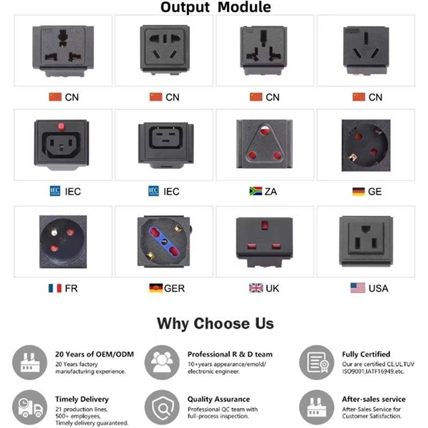
Smart PDUs & Power Distribution
Intelligent PDUs with remote monitoring, per-outlet switching, and environmental sensors.
Shelters & Network Cabinets
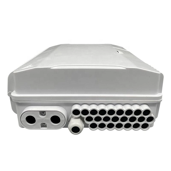
Prefabricated telecom shelters, emergency comms shelters, and network cabinets with cable management.