GUIDE CABLE TRAYS TECHNICAL
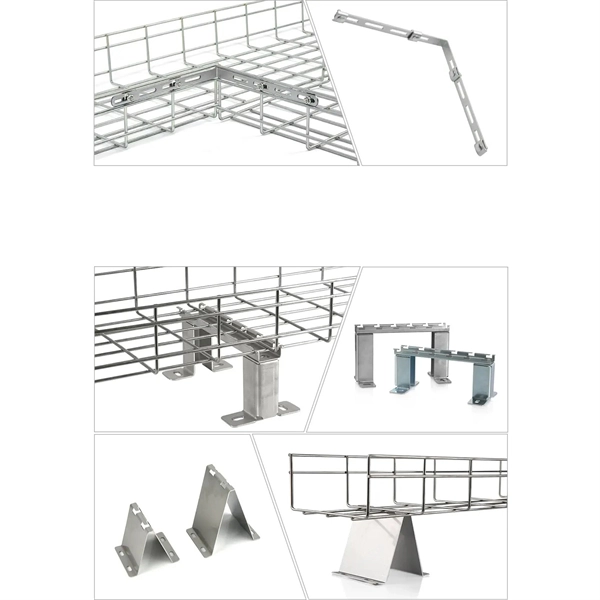
When fitting cable trays and their accessories, the products are cut on site to create changes of direction, adjust sections, etc. Damage can also occur during handling; as a result, both the
Cable Tray Technical Guide A practical guide to product selection
Cable tray length is selected based on the load to be supported, the distance between the supports (also referred to as the span), and handling and installation constraints.
Cable tray manual
Some of these criteria include the required load that the cable tray must support, the distance between the cable tray supports, and ease of handling and installation.
A Guide to Installing and Supporting Electrical Cable Trays
This guide covers the critical steps, from selecting the right electrical cable tray and performing accurate cable fill calculations to managing a safe cable pull through and ensuring all bonding and grounding
IEC Standard for Cable Tray: Complete Technical Guide
For proper installation, design, and maintenance, adherence to international standards is essential. One of the most recognized frameworks globally is the IEC standard for cable tray
16115 Cable Tray
Location of tray shall be dimensioned and closed obstructions shown and noted. Drawings shall include sections of corridors and of areas where obstructions require special coordination, showing the tray
Cable Tray Dimensions Guide: Standard Sizes, Tray
We will first explain standard cable tray dimensions used across the industry, then examine how dimensions vary by tray type, and finally show how to
CABLE TRAY SYSTEMS GUIDE
Some applications may require the cable tray to support the weight of a single, dead object in addition to the cable loads. Specifications typically require this to be applied at the midpoint of the span between
Standard for Installing Metal CableTraySystems
These guidelines and information do not intend to cover all details or variations in cable tray systems nor provide for every possible installation contingency.
Technical Specification for Cable tray installation and cable laying
Approval of IPR shall be obtained for site preparation and marking the cable tray routes and locations of cable tray support before proceeding with the erection and installation work.
Cable Tray Dimensions Guide: Standard Sizes, Tray Types & Sizing
We will first explain standard cable tray dimensions used across the industry, then examine how dimensions vary by tray type, and finally show how to calculate and select the correct
Complete cable tray manual for electrical engineers and designers
As more circuits are added, the cable tray installation zone will increase only a few inches. The space required for the additional conduits needed would be much greater.
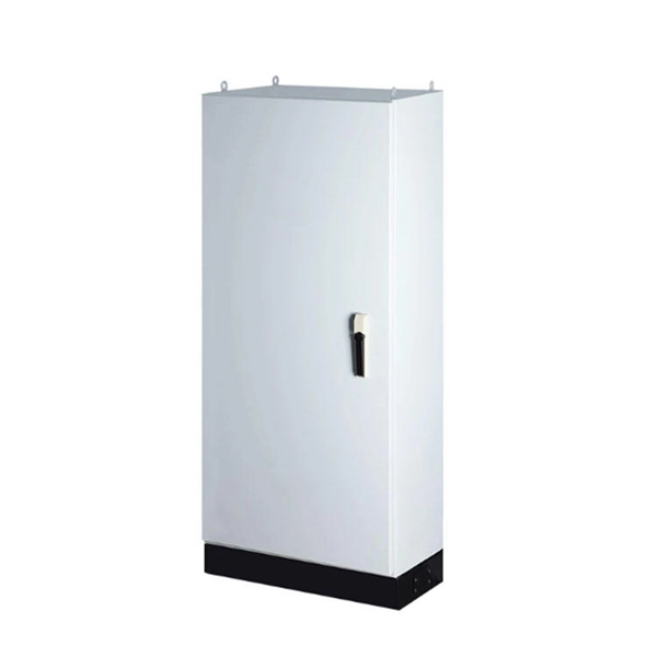
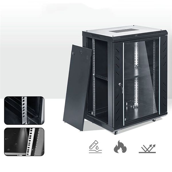
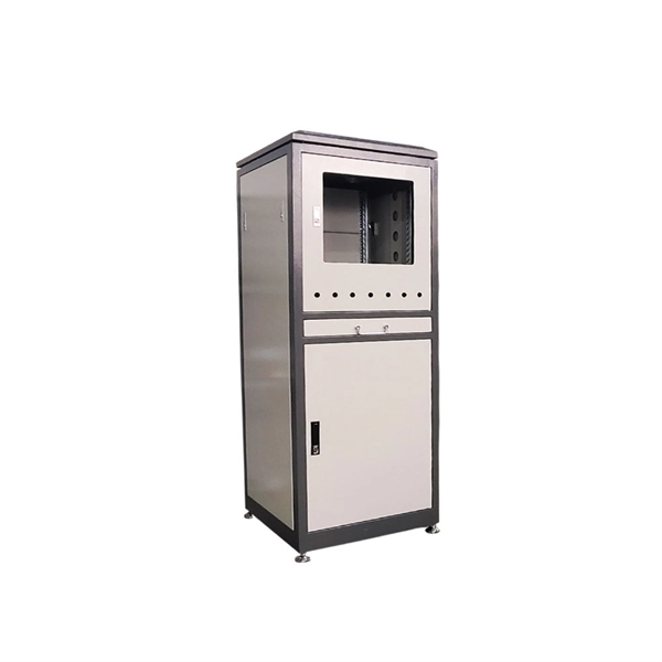
Telecom Racks & Cabinets
19-inch racks, wall-mount cabinets, open frames with high load capacity and seismic rating.
Outdoor Climate Cabinets
IP55/IP66 outdoor enclosures with integrated cooling/heating, -40°C to +55°C operation.
Smart PDUs & Power Distribution
Intelligent PDUs with remote monitoring, per-outlet switching, and environmental sensors.
Shelters & Network Cabinets
Prefabricated telecom shelters, emergency comms shelters, and network cabinets with cable management.