Optimizing Optical Module Performance
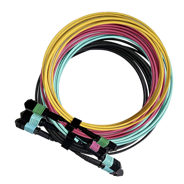
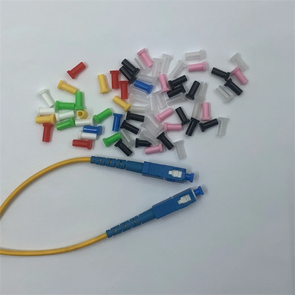
Three villains are lurking in your fiber: Optical Loss: Light gets absorbed, scattered, or leaked as it travels. Dirty connectors? Bent cables?
Use of Advance Packaging to Reduce Optical Module PCB Losses
Advance optical modules are using mSAP (modified Semi Additive Package) to save cost and power – mSAP was developed in the last 7-10 years in support of smart phones and watches.
Troubleshooting and Repairing Optical Transceiver Failures in
Have you ever experienced an unexpected network outage due to the failure of an SFP/SFP+ optical transceiver?
Optical Module Channel Loss Resistance Explained
It represents the module''s ability to operate reliably across an optical channel with defined insertion losses caused by fiber length, connectors, splices, and passive components.
Troubleshooting Your Optical Transceiver: A
However, like any other electronic component, optical transceivers can encounter issues that may affect network performance. In this guide, we''ll delve
2025 Understanding TX/RX Power Range on SFP Modules for Network
In real-world networks, signal loss can occur due to various issues such as poor fiber splicing, dirty connectors, or cable damage. If the TX/RX power range is not well-matched or
4 Optical Loss Budgets
Using the optical loss characteristics for the Cisco ONS 15540 components, you can calculate the optical loss between the transmitting laser on one node and the receiver on another node.
Troubleshooting Your Optical Transceiver: A Comprehensive Guide
However, like any other electronic component, optical transceivers can encounter issues that may affect network performance. In this guide, we''ll delve into common optical transceiver
Optical Module Performance: Key Power and Sensitivity Metrics
In modern optical communication systems, optical modules serve as the core photoelectric conversion components whose performance metrics directly impact the efficiency and
Recommendation for Module Plug Board Losses
This consensus proposal recommends allocating 3.8 dB loss for the plug board to support varity of advanced mSAP implementation as well as conventional implementations with 1st level package
Key Differences Between Insertion Loss and Return Loss in Optical Modules
Learn the difference between insertion loss and return loss in optical transceivers, their impact on performance, measurement methods, and LINK-PP product guidance.
16 Tips to Troubleshoot Your Optical Transceiver Issues
If the optical power is too high, it will cause signal distortion, packet loss, and even damage to the optical module. If the optical power is too low, it will cause the receiving end to receive a
The Most Comprehensive Guide Of Optical Modules
Overloading of optical power, also known as saturated optical power, refers to the maximum allowable optical power that the optical module can withstand without causing signal
Key Differences Between Insertion Loss and Return
Learn the difference between insertion loss and return loss in optical transceivers, their impact on performance, measurement methods, and LINK-PP
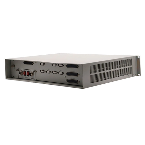
Telecom Racks & Cabinets
19-inch racks, wall-mount cabinets, open frames with high load capacity and seismic rating.
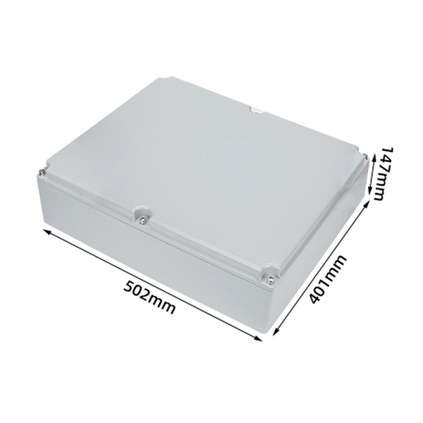
Outdoor Climate Cabinets
IP55/IP66 outdoor enclosures with integrated cooling/heating, -40°C to +55°C operation.
Smart PDUs & Power Distribution
Intelligent PDUs with remote monitoring, per-outlet switching, and environmental sensors.
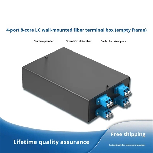
Shelters & Network Cabinets
Prefabricated telecom shelters, emergency comms shelters, and network cabinets with cable management.