AF_UnifiedCat_Interior_PRINT
Trough tray can be cut to length with a reciprocating saw fitted with a fine metal cutting blade. Mark three sides of the tray using a square and make allowances to keep mounting hole slots in position for
CABLE TRAY SYSTEMS GUIDE
Hubbell''s NEXTFRAME® Ladder Tray is the effective and widely used cable runway that supports and delivers bundles of cable between cabinets, racks, and closets, along walls, and suspended from
LEGRAND CABLE TRAYS TECHNICAL GUIDE
If it has excellent electrical continuity and is integrated in the installation''s equipotential bonding system, a metal cable tray reduces the coupling''s impact and thus contributes to good EMC of the electrical
Cable Tray / Ladder Tray INSTALLATION PowerTray
General Installation Guidelines: latest NEMA standards and local building codes. Trough tray field support and frequency depends on the weight and const ction (splice locations, e bow fittings, etc.)
B-Line series Cable Tray Design Considerations
For ladder or ventilated trough trays, the total sum of the cross-sectional areas of all the cables to be installed in the cable tray must be equal to or less than the allowable cable area for the tray width, as
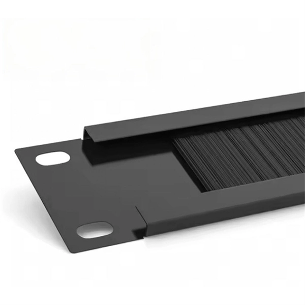
Wire and Cable Management
Using a unique joining method that mechanically locks components together without fasteners or heat, this wiring trough ships completely assembled to save both time and labor. Designed for indoor use,
Cable Tray Fill Calculator (NEC 392)
Select your tray type (ladder, ventilated trough, solid bottom, or channel), enter the tray width and usable depth, then add cables by size and quantity. The calculator
Cable Tray Ladder Trunking Wire Basket Installation Guidelines
Cable tray should not be laid directly on the floor or roof. It should be mounted far enough off the floor or roof to allow the cables to exit through the bottom of the cable tray.
A Guide to Installing and Supporting Electrical Cable Trays
Determine Maximum Fill Area: Consult NEC Table 392.22 (A) to find the maximum permissible fill area for the specific width and type of your cable tray. Sum the Cable Areas: Add up the cross-sectional
One-piece tray
For example, the first selection issue is the environment to which the cable tray will be subjected. This selection will lead to the best material for your application.
INSTALLATION GUIDE
When a separate bonding conductor is required to supplement the bonding offered by a ferrous metallic tray system it must be installed inside the tray along with the circuit conductor.
Legrand Trough P31 Trough / Cable Tray Installation Guide
This installation guide provides comprehensive instructions for the assembly, cutting, and installation of the Trough (P31) cable tray system.
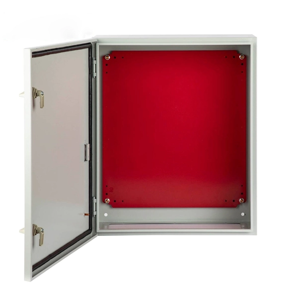
Telecom Racks & Cabinets
19-inch racks, wall-mount cabinets, open frames with high load capacity and seismic rating.
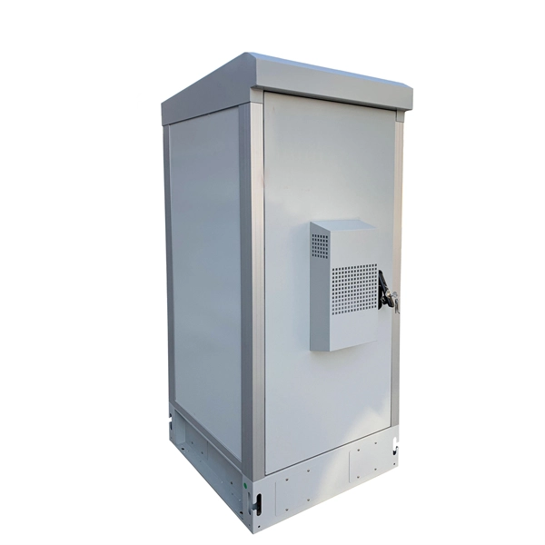
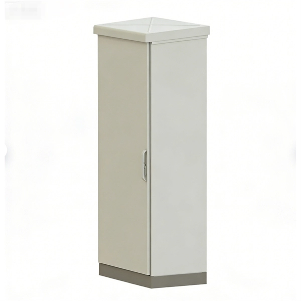
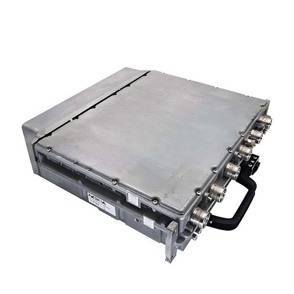
Outdoor Climate Cabinets
IP55/IP66 outdoor enclosures with integrated cooling/heating, -40°C to +55°C operation.
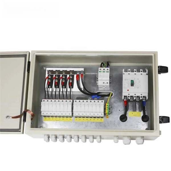
Smart PDUs & Power Distribution
Intelligent PDUs with remote monitoring, per-outlet switching, and environmental sensors.
Shelters & Network Cabinets
Prefabricated telecom shelters, emergency comms shelters, and network cabinets with cable management.