Optical fiber coupling loss
Ideally, optical signals coupled between fiber optic components are transmitted with no loss of light. However, there is always some type of imperfection present at fiber optic connections that causes
#1 Cause of Fiber Optic Cabling Failures
Uncover the #1 cause of fiber optic system failures with trueCABLE expert Ben Hamlitsch. Discover why clean connectors are crucial and how to
How to Identify and Fix Damaged Fiber Optic Connectors
Learn about the common types and causes of fiber optic connector damage, the tools and methods to inspect and test them, and the best practices to prevent and fix them.
Optocoupler Failures
Gideon Analytical Laboratories received two failed photocouplers for failure analysis. These photocouplers feature a high isolation voltage, high-speed switching, and
Optoelectronic Devices Failure Mechanisms and Anomalies
Table 2 summarizes some typical failure modes and mechanisms for optical fibers, cables and connectors. See the section on Connectors for some connector failure concerns, as applicable, to...
Diagnosing and Solving Common Optical Transceiver Failures
Unlock insights into optical transceiver issues: docking failures, troubleshooting steps, and protective measures for optimal performance and longevity.
8 Signs Your High-Voltage Opto-Coupler Needs Replacing
Find out if your high-voltage opto-coupler needs replacing with these signs of wear and tear.
Optical Connector Care
Damage to fiber-optic input connectors (as well as connectors on calibration and verification devices, test ports, cables, and other devices) can degrade measurement accuracy and damage instruments.
Optical Coupler Failure Analysis
Gideon Analytical Labs received four Fairchild 74OL6000 field failed Optocouplers along with three good (virgin green dot) devices in which a comparison could be done. The LSTTL input
How to Identify & Prevent Optical Fiber Cable Damage
Learn how to detect and repair damaged fiber optic cables. Visual checks, OTDR testing, IEC compliance, and waterproof maintenance tips for reliability.
Demystifying Optical Transceiver Failures: Common Issues
These compact devices convert electrical signals to optical signals and vice versa, enabling data transmission over fiber optic cables. While generally reliable, failures do occur, leading
Factors Influencing the Optical Performance of Fiber Optic
One disadvantage of using connectors is that optical performance may be compromised due to the introduction of unwanted and uncontrollable factors, such as contaminations, scratches, etc.
1950 nm 1x2 Polarization-Maintaining Fiber Optic Couplers / Taps
All of these 1950 nm couplers have a maximum power handling of 1 W with connectors or bare fiber and a maximum power handling of 5 W when spliced (see the Damage Threshold tab for more details).
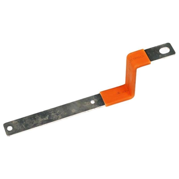
Telecom Racks & Cabinets
19-inch racks, wall-mount cabinets, open frames with high load capacity and seismic rating.
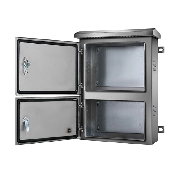
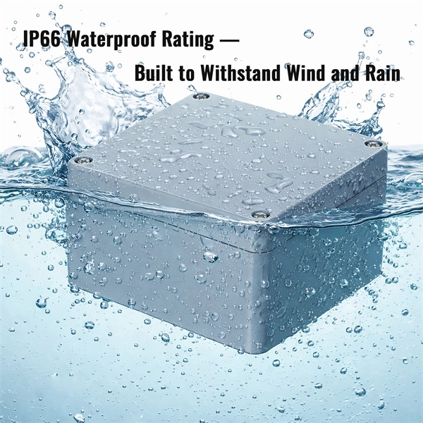
Outdoor Climate Cabinets
IP55/IP66 outdoor enclosures with integrated cooling/heating, -40°C to +55°C operation.
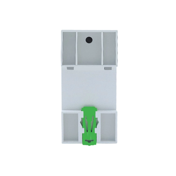
Smart PDUs & Power Distribution
Intelligent PDUs with remote monitoring, per-outlet switching, and environmental sensors.
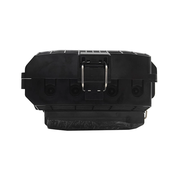
Shelters & Network Cabinets
Prefabricated telecom shelters, emergency comms shelters, and network cabinets with cable management.