Understanding Signal Attenuation in Fiber Optics and How to Manage It
Optical attenuation is the gradual loss of flux (light intensity) as an optical signal travels through a fiber. Measured in decibels (dB), it''s the logarithmic ratio of the output power to the input
Optical Fiber Loss and Attenuation | MEETOPTICS Academy
Attenuation refers to the amount of signal loss as it travels down the fiber, typically expressed in dB/km. Losses can be caused by scattering, absorption, dispersion & bending.
Fiber Loss Analysis Guide
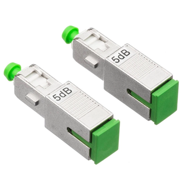
Multimode connectors typically have losses of 0.2 to 0.5 dB, while factory-made single-mode connectors have losses of 0.1 to 0.2 dB. Field-terminated single-mode connectors may have
Fiber Loss Limits – How Much Loss Is Too Much in Fiber Optic Testing?
Singlemode Fiber: Loss per connector should not exceed 0.5 dB, and loss per kilometer should be less than 0.4 dB. For example, a 500m singlemode link with two connectors would be
Understanding Fiber Optic Signal Loss & Attenuation
Learn about fiber optic signal loss, its causes, measurement techniques, and strategies to reduce attenuation for high-speed, reliable network performance.
The FOA Reference For Fiber Optics
The attenuation of the optical fiber is a result of two factors, absorption and scattering. The absorption is caused by the absorption of the light and conversion to heat by molecules in the glass. Primary
Understanding Fiber-Optic Cable Signal Loss, Attenuation, and
To determine the power budget and power margin needed for fiber-optic connections, you need to understand how signal loss, attenuation, and dispersion affect transmission.
Optical Fiber Power Loss and Automatic Power Reduction: A
Comprehensive guide on optical power loss in fiber optics and Automatic Power Reduction (APR). Learn attenuation causes, formulas, tables, and strategies to reduce fiber loss for
Basic Principles of Fiber Optics Series: Attenuation
Discover the causes and effects of attenuation in fiber optic cables. Learn about scattering, absorption, bending losses, and how to limit signal degradation.
Understanding Signal Attenuation in Fiber Optics and
Optical attenuation is the gradual loss of flux (light intensity) as an optical signal travels through a fiber. Measured in decibels (dB), it''s the
Fiber Optic Attenuation Calculator | Fiberopticx
This calculator helps you estimate the total attenuation (signal loss) in a fiber optic cable link. Here are the details and instructions about each field and how they contribute to the calculation:
Intrinsic and Extrinsic Attenuation in Fiber Optic Cables
The typical loss values for extrinsic attenuation are approximately 0.25 dB to 0.75 dB for connector losses, and around 0.05 dB to 0.30 dB for bad splices. Values higher than these recommended ones
Attenuation in Optical Fibers: A Comprehensive Guide
Protecting your data has never been more important. My cyber security blog is here to help you stay ahead of the game. I cover a wide range of topics,
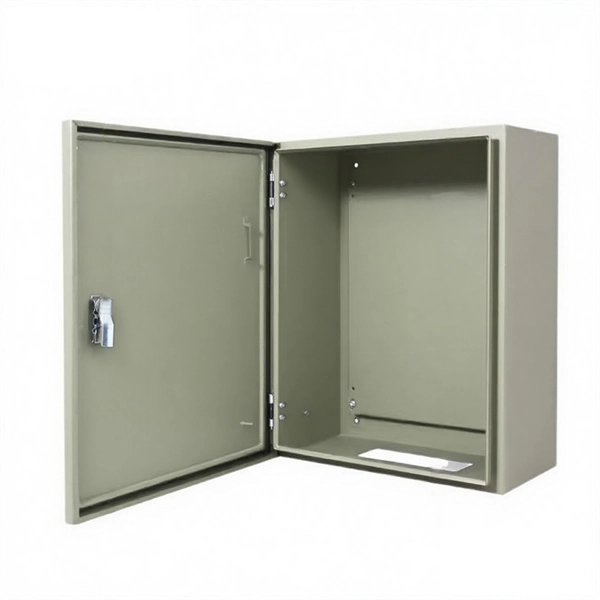
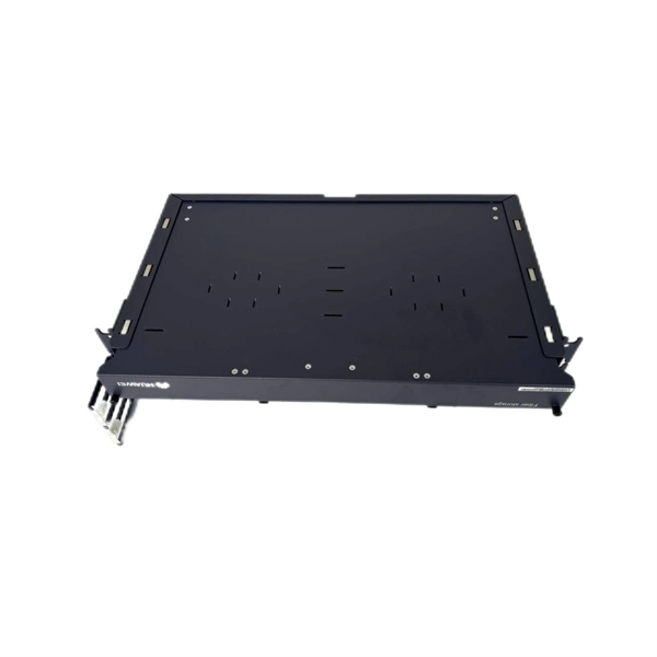
Telecom Racks & Cabinets
19-inch racks, wall-mount cabinets, open frames with high load capacity and seismic rating.
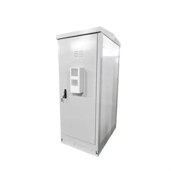
Outdoor Climate Cabinets
IP55/IP66 outdoor enclosures with integrated cooling/heating, -40°C to +55°C operation.
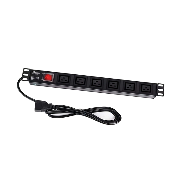
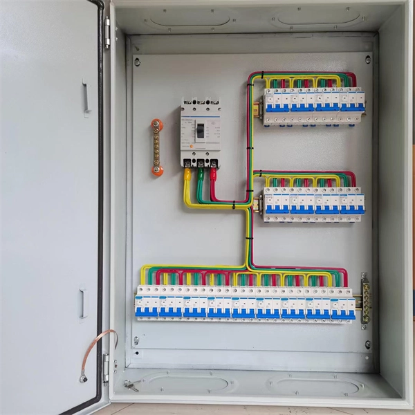
Smart PDUs & Power Distribution
Intelligent PDUs with remote monitoring, per-outlet switching, and environmental sensors.
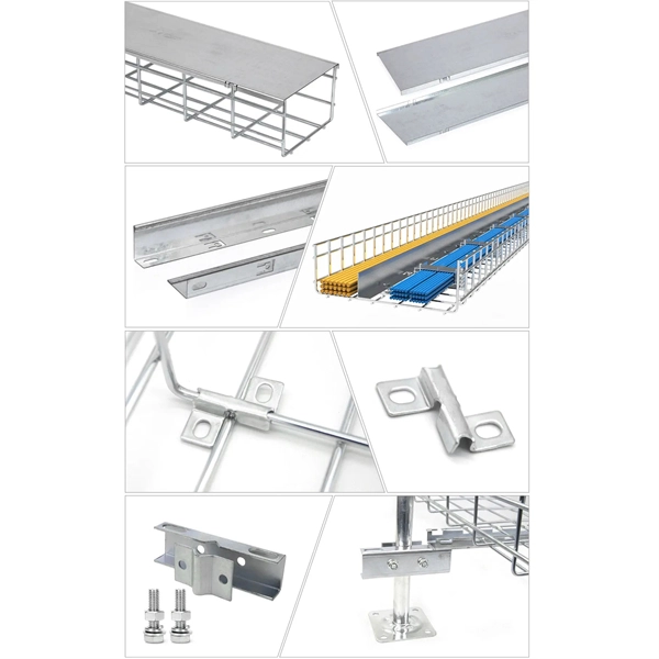
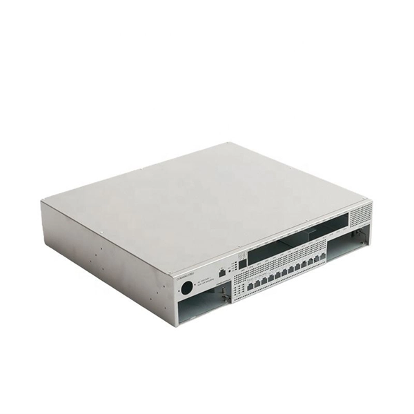
Shelters & Network Cabinets
Prefabricated telecom shelters, emergency comms shelters, and network cabinets with cable management.