Basic Knowledge about Split Ratio and Insertion Loss of Optical Splitter
In summary, understanding split ratio and insertion loss of optical splitter is vital for optimizing fiber optic networks. The split ratio dictates power distribution among ports, impacting
Understanding Optical Splitter Loss
Understanding splitter ratios and insertion loss is fundamental to building a reliable fibre optic network. The key takeaway is that every split reduces optical power, and this loss must be
PLC Splitter and download the loss chart of PLC splitter
A splitter with 1×2 certain ratio configuration means that it has one input and two outputs. There are 1×4 plc splitter, 1×8 plc splitter, 1×16 plc splitter, 1×32 splitter, and so on. Here is a table of
How to Calculate Optical Splitter Loss
Understanding optical splitter loss isn''t just about plugging numbers into a calculator. It''s about knowing what factors contribute to that loss, how manufacturers specify it, and how it impacts
-Teleweaver in China
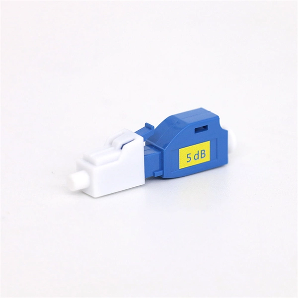
The optical insertion loss is the loss of an optical signal resulting from the insertion of a component such as connector or splice in an optical fiber system. In order to conserve the power budget of a PON
Ultimate Guide 2023: PLC Splitter / FBT Fiber Splitter Loss Chart
How to measure fiber optic splitter insertion loss with calculation? The maximum allowable insertion loss for an optical splitter used in a PON system can be determined by using the
Channel insertion loss for 1x64
The presented channel insertion loss does not include optical margins for component / fiber ageing, repair, or dispersion penalties.
Differences Between 1x2 to 1x64 PLC Splitter Applications
Each doubling of the split ratio increases optical insertion loss by approximately 3 dB. Therefore, 1×2 has low loss, while 1×64 introduces significantly higher loss, affecting maximum
Optical Splitter Loss Calculator
Estimate optical splitter losses for fiber building projects fast. Include connectors, splices, excess loss, and margin safety. Export results to reports for clean client handoffs.
Channel insertion loss for 1x64 and 1x128 split EPONs
Insertion loss of ODN: ODN degradation, repair/rerouting and IL difference/variations – the estimation of these values is difficult, because these depend on operator''s policy.
Telecom Racks & Cabinets
19-inch racks, wall-mount cabinets, open frames with high load capacity and seismic rating.
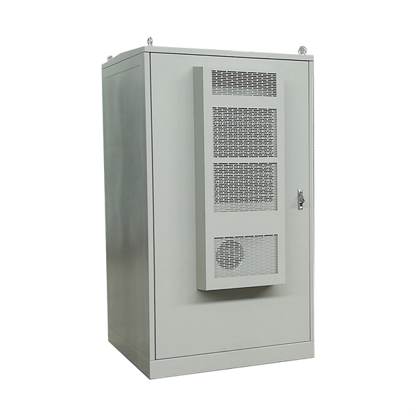
Outdoor Climate Cabinets
IP55/IP66 outdoor enclosures with integrated cooling/heating, -40°C to +55°C operation.
Smart PDUs & Power Distribution
Intelligent PDUs with remote monitoring, per-outlet switching, and environmental sensors.
Shelters & Network Cabinets
Prefabricated telecom shelters, emergency comms shelters, and network cabinets with cable management.