
35kV RMU Busbar Failure Due to Installation Errors Analysis
When the fault occurred, the voltage of phases A and C on the 35kV busbar No.1 rose to line voltage while the voltage of phase B approached zero. This is characteristic of a typical single-phase metallic
Medium Voltage: Line to Ground Circuit | Information by Electrical
System voltage is 34.5kv - 19.9 kv. As I''m not familiar with high voltage maybe this is actually a typical installation, but it seemed funny to me. It looks to be installed in accordance with
Personal Protective Grounding in Substations
Large bus bar clamps with integral rated studs are relatively new to the industry. They do not have a cable/ferrule attached and are installed onto the large buses using a grip-all clamp stick.
Bus Bars and Bus Ducts Design Requirements ANSI C37.23
Bolted bus bar connections shall be made with the bolts passing through the bus bars in a way that they can be properly torqued and locked in place to maintain full and uniform pressure under all operating
GROUND GRID SPECIFICATIONS
Each Power Circuit Breaker or Power Transformer having a bushing Voltage Transformer on the tank shall have the Voltage Transformer provided with a separate ground lead, independent of the
Insulation of bus bars at 35 kV | Eng-Tips
Cables have grounded shields; other insulators are mounted to grounded surfaces. Cover a substation bus bar with a really good insulator but don''t provide a grounded shield and you''ll find
What''s in the Code? Applying the NEC to medium
These systems are called medium-voltage. Those of more than 35 kV are high-voltage. The NEC provides several rules related to grounding of these systems and equipment. Part X of
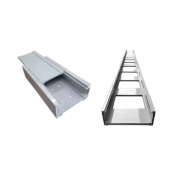
Busway Medium Voltage
The conductors are adequately separated and insulated from each other and grounded by insulating bus supports. Each conductor for 2400 V service and above is insulated with a fluidized bed epoxy
Distribution System Neutral Grounding Methods and Transformer
Method: A high impedance reactor is inserted between the transformer neutral and ground. All other neutrals are isolated from ground. The reactor is sized (tuned) to resonate with the zero sequence
35kV Substation Electrical Design
The document then discusses the electrical main wiring designs for the substation, including selecting the main transformer capacity and type, designing the substation, and selecting a bus bar scheme.
Telecom Racks & Cabinets
19-inch racks, wall-mount cabinets, open frames with high load capacity and seismic rating.
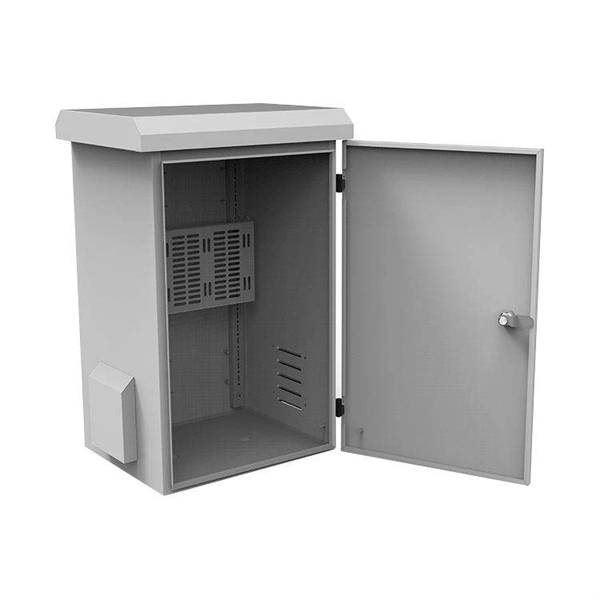
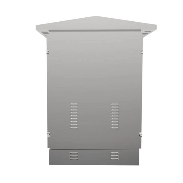
Outdoor Climate Cabinets
IP55/IP66 outdoor enclosures with integrated cooling/heating, -40°C to +55°C operation.
Smart PDUs & Power Distribution
Intelligent PDUs with remote monitoring, per-outlet switching, and environmental sensors.
Shelters & Network Cabinets
Prefabricated telecom shelters, emergency comms shelters, and network cabinets with cable management.