How Back Reflection and Insertion Loss Affects Data
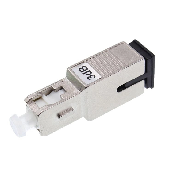
It is expressed in negative dB and used to describe any process that causes light to change direction in fiber and return to the source. This occurs most often at connector interfaces.
Basic Principles of Fiber Optics Series: Optical Return Loss/Reflectio
Optical return loss is the amount of light that is reflected back to the source, this reflected light is measured at each connector and splice at each point over the entire fiber link. This is always
Return loss calculator for testing fiber optic cables
The term Reflectance describes a single reflection in an optical assembly. Reflectance occurs at point discontinuities, for example connector interfaces, splice interfaces, etc. Typically, Return Loss is
Fiber Connector Loss Causes, Effects, and Solutions
Fiber connector loss is a significant factor in the performance of fiber optic networks, but it is manageable. By understanding its causes, recognizing its effects, and taking proactive steps to
Fiber Optic Link Loss Troubleshooting | NFM Consulting
Key Takeaway Systematic approach to diagnosing fiber optic link loss in industrial communication networks. Covers OTDR testing, connector inspection, splice evaluation, bend loss
How Back Reflection and Insertion Loss Affects Data
What Is Back Reflection?How Can I Minimize The Negative Effects of Back Reflection?What Is Insertion Loss?How Can I Minimize The Negative Effects of Insertion Loss?Back reflection (also referred to as optical return loss or ORL) is an undesirable characteristic that is primarily a concern for singlemode fiber. It is expressed in negative dB and used to describe any process that causes light to change direction in fiber and return to the source. This occurs most often at connector interfaces. Optical return lo...See more on cablexpress Published: Mar 21, 2023The Fiber Optic Association
The FOA Reference For Fiber Optics - The Fiber Optic
Below is a diagram of a typical setup for reflectance or return loss tests of connectors or patchcords per industry standards (TIA FOTP-107 or IEC 61300-3-6) using a
Connector Loss, Return Loss, and Reflectance – “Highs and Lows”
Optical loss (for connectors), sometimes called attenuation, is simply the reduction of optical power induced by transmission through a medium such as a pair of fiber optic connectors.
Insertion loss: Are you positive it''s negative?
A negative insertion loss indicates a problem, one of which is often improper reference setting. For example, if a reference cable is dirty when setting the zero reference, and then cleaned before
The FOA Reference For Fiber Optics
Below is a diagram of a typical setup for reflectance or return loss tests of connectors or patchcords per industry standards (TIA FOTP-107 or IEC 61300-3-6) using a light source and power meter.
Optical Fiber Loss and Attenuation | MEETOPTICS Academy
Insertion loss, also referred to as connector losses, refers to the loss of optical power that occurs when light is transmitted through a component, such as a connector, splice, coupler, or any other device
Telecom Racks & Cabinets
19-inch racks, wall-mount cabinets, open frames with high load capacity and seismic rating.
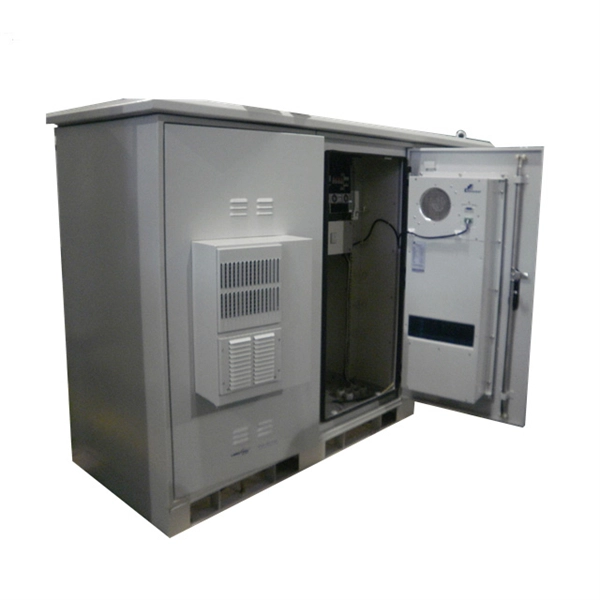
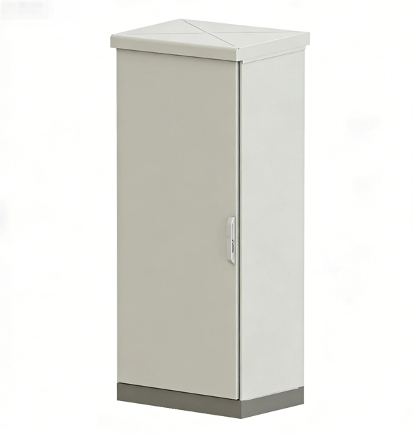
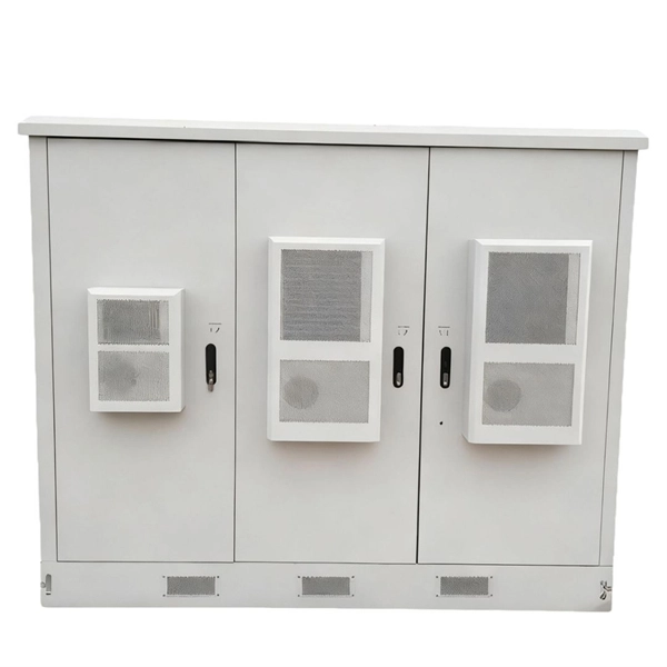
Outdoor Climate Cabinets
IP55/IP66 outdoor enclosures with integrated cooling/heating, -40°C to +55°C operation.
Smart PDUs & Power Distribution
Intelligent PDUs with remote monitoring, per-outlet switching, and environmental sensors.
Shelters & Network Cabinets
Prefabricated telecom shelters, emergency comms shelters, and network cabinets with cable management.