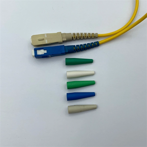
Fiber Optic Connectors Figure 1
Figure 1 - Parts of a Fiber Optic Connector from the splice in its ability to be disconnected and reconnected. Fiber optic connector type are as various as the applications for which they were
Fiber Optic Circuit – Transmitter and Receiver
The primary fiber optic receiver circuit diagram can be seen in the upper section of the below diagram, the output filter circuit is drawn just below the receiver circuit.
Fibre Optic Cable & Connector Guide
All fibre optic connectors have four basic components, which are the ferrule, connector body, cable, and coupling device. They have been widely used in the termination of fibre optic cables, such as fibre
TR-3552: Optical network installation guide
Devices are connected in single or dual (counter rotating) rings. With counter-rotating rings (most common), two rings transmit in opposite directions. If one device fails, one ring will automatically loop
Working with MTP /M
Patch cords made with individual single fiber connectors at each end allow the flexibility for connections to be “swapped” when a polarity reversal is required.
Fiber Optics III
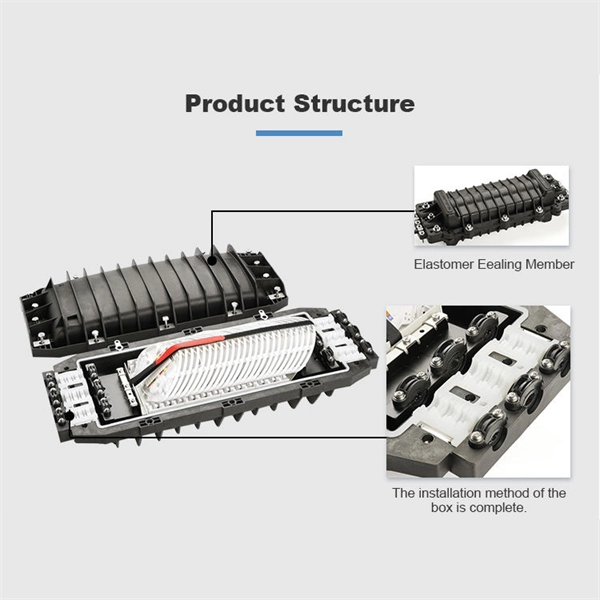
A fiber optic splice is a permanent fiber joint whose purpose is to establish an optical connection between two individual optical fibers. System design may require that fiber connections have specific
13-SDMS-01 REV. 00 SPECIFICATIONS FOR FIBER OPTIC
Adapter or Through-Connector: A device, either mounted on a patch panel or used in-line, to mechanically align, couple and mate or join two plug-in optical connectors of either the same or
CAD Drawings
Download CAD drawings for our Fiber and Copper products Search by part number or description such as CAT5, CAT6, OSP, etc. Sort by any of the table headers. Use the drop down menu to filter by
OPTICAL FIBER JOINTS & CONNECTIONS
Expanded-Beam Connectors Utilize interposed optics at the joint in order to expand the beam from the transmitting fiber end before reducing it again to a size compatible with the receiving fiber end.
VHO-HMterm
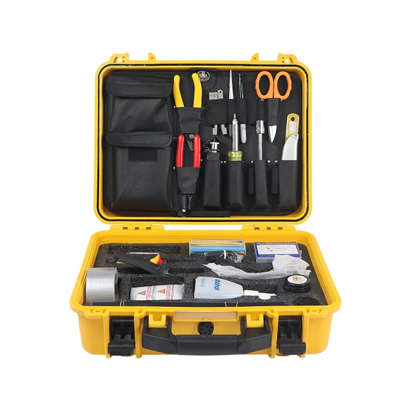
This FOA virtual hands-on (VHO) tutorial on fiber optics covers fiber optic cable termination using the 3M HotMelt connector process. It is copyrighted by the FOA and may not be distributed without FOA
Module 3 ber couplers and connectors.pptx
The document outlines the syllabus for a module on fiber couplers and connectors in optical fiber communications, focusing on fiber joint types, optical loss, and splicing techniques. It details both
Optical Fiber connectors | PPTX
Proper connectors are important for achieving low insertion loss while providing easy installation and connection/disconnection of fibers. - Download as a PPTX, PDF
Schematic of Optical fiber connector | Download
This article proposed a method for final assembly of optical fiber cables based on the needs of satellite installation of optical fiber cables, the structural features of
Fiber Optic Connector Chart
The termination on the fiber optic cable itself is called an FDDI connector, or is also known as an MIC (Media Interface Connector) connector. It contains two ferrules in a large, bulky plastic housing that
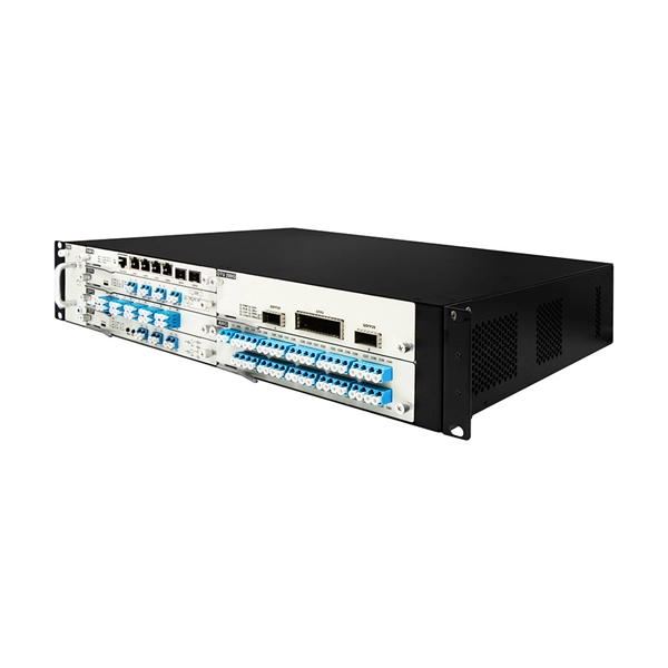
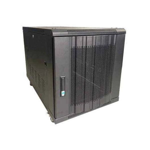
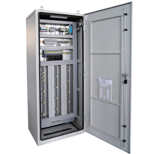
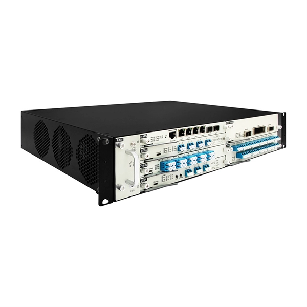
Telecom Racks & Cabinets
19-inch racks, wall-mount cabinets, open frames with high load capacity and seismic rating.
Outdoor Climate Cabinets
IP55/IP66 outdoor enclosures with integrated cooling/heating, -40°C to +55°C operation.
Smart PDUs & Power Distribution
Intelligent PDUs with remote monitoring, per-outlet switching, and environmental sensors.
Shelters & Network Cabinets
Prefabricated telecom shelters, emergency comms shelters, and network cabinets with cable management.