Schematic diagram of fiber-optic cable layout and
The article presents research on the performance of different distributed fibre optic sensing (DFOS) tools, including both layered cables and monolithic composite
Sheath Removal and Stripping of 8 and 12-Fiber Ribbon
4.1 Determine the cable strip lengths (i.e., the lengths of jacket to remove, and aramid yarn to leave) from the instruct-ions provided with the connectors, or other fiber optic devices you are installing on
The FOA Reference For Fiber Optics
The choice of outside plant fiber optic (OSP) components begins with developing the route the cable plant will follow. Once the route is set, one knows where cables will be run, where splices are located
Fiber U Lesson Plan: Basic Fiber Optic Skills Lab
In this lesson, we will identify and examine cables, then prepare them for splicing or termintion by stripping the cable to expose the coated fibers. Finally we will strip fibers, the final step before
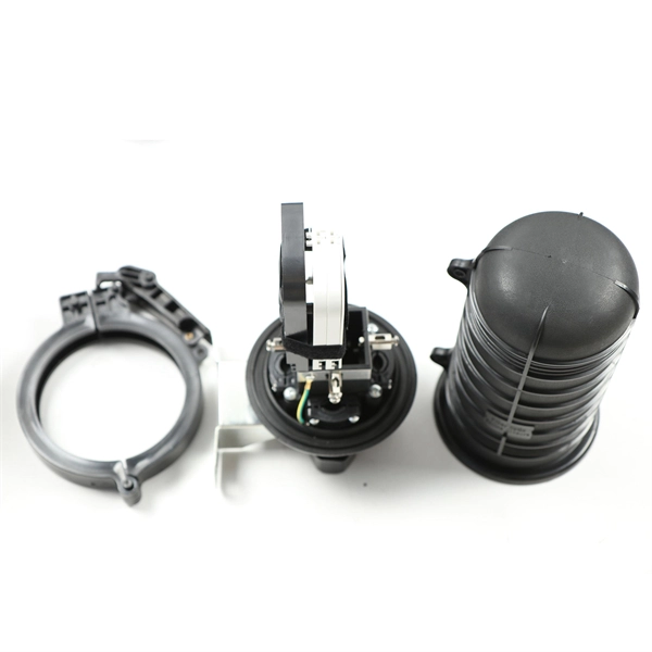
Figure 8 Fiber Optic Drop Cable
The instructions in this document explain how to prepare end openings of the Prysmian Figure 8 Fiber Optic Drop Cable for termination. The document also covers applications notes including the use of
FIBER OPTICS
When a fiber optic cable is routed with electric infrastructure (for example, within the Downtown Ductbank) the route maps should show its duct assignment. Construction detail sheets should clearly
Fiber Optic Cable Installation and Handling Instructions
The information contained in this manual should serve as a guide to proper handling, installing, testing, and for troubleshooting problems with fiber optic cables.
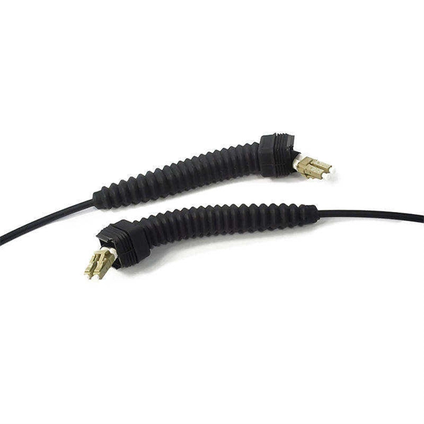
Easy-Strip Fig8 Outdoor Indoor Flat Drop cable-ARP/FRP/SW
The 2 ARP and the fibres are embedded in an outer jacket made of LSZH material indented at the fibre''s location, and the messenger wire is jointed to the small side of the cable in a typical figure 8
Use the Proper Strip Template When Stripping for Connectorization
Most connector will have a “stripping template” available to describe the optimum strip lengths for each part of the cable. Be sure to ask your connector supplier for the proper strip charts
Fiber Optic Route Surveys
We use CAD software to prepare drawings for fiber optic cable networks using our clients'' data (e.g. a geographic map or a geospatial survey).
Schematic diagram of fiber-optic cable layout and sensing. Reprinted
The article presents research on the performance of different distributed fibre optic sensing (DFOS) tools, including both layered cables and monolithic composite sensors.
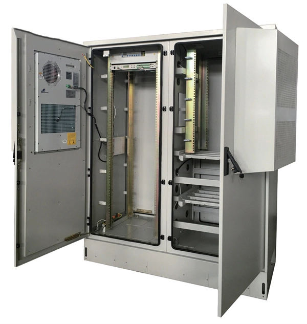
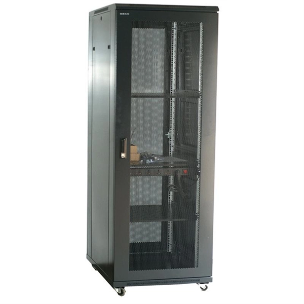
Telecom Racks & Cabinets
19-inch racks, wall-mount cabinets, open frames with high load capacity and seismic rating.
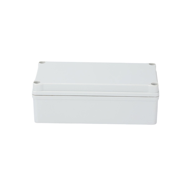
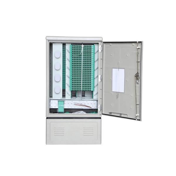
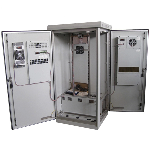
Outdoor Climate Cabinets
IP55/IP66 outdoor enclosures with integrated cooling/heating, -40°C to +55°C operation.
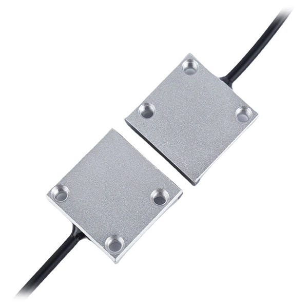
Smart PDUs & Power Distribution
Intelligent PDUs with remote monitoring, per-outlet switching, and environmental sensors.
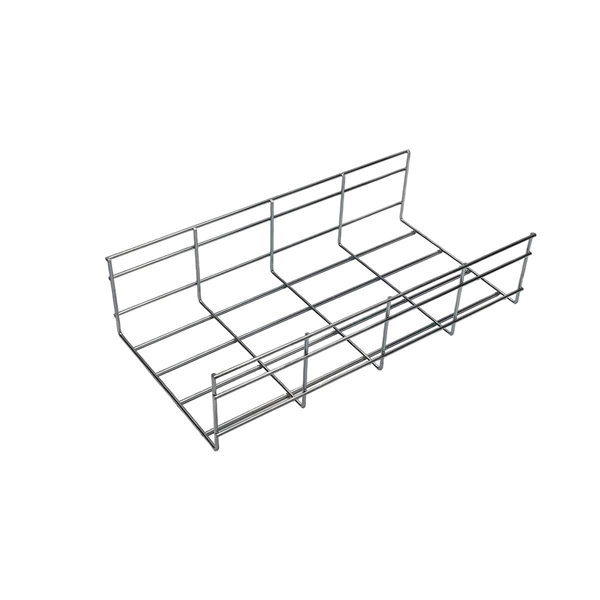
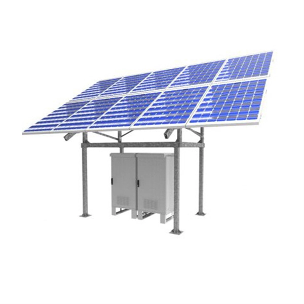
Shelters & Network Cabinets
Prefabricated telecom shelters, emergency comms shelters, and network cabinets with cable management.