Priori information analysis of optocoupler accelerated degradation
In this paper, the optocoupler failure mechanism verification test is designed and the experimental results are analyzed and the prior information is obtained.
Good Luck To You!
Poor layout can lead to problems like noise interference, crosstalk, or signal degradation. Routing high-current paths too close to the optocoupler or failing to properly decouple the power
A Short De-mystification of Optocouplers
Optocouplers generally suffer poor performance in high-frequency applications due to their limited bandwidth. Check the specs of your specific optocoupler and make sure that the speed
Understanding the Causes of Slow Response in 6N137 Optocouplers
In this analysis, we will explore the common causes of slow response in 6N137 optocouplers, identify the underlying factors, and provide a step-by-step solution guide to fix these
How to Diagnose and Repair 6N137SDM Optocouplers_ A Guide for
Poor Signal Transfer: A decrease in the efficiency of light transmission can occur due to the degradation of the optical components over time. This might lead to weak signals or complete
Proton Damage in Linear and Digital Optocouplers
Optocoupler failures occurred on the Topex-Poseidon spacecraft after about two years of operation. Later work in the laboratory showed that the failures were due to extreme sensitivity of LEDs within
Failure mechanisms and package reliability issues in optocouplers
The unique construction, materials, and interfaces in optocouplers that make their failure modes and mechanisms different. This paper presents a definite and comprehensive research on
ANO006 | Lifetime of Optocouplers
When considering the components themselves, some can fail completely or degrade in performance with time. For optocouplers, the performance (Current – Transfer - Ratio) degrades over time
Make sure your optocoupler is properly biased
When you are designing an isolated feedback network, you must consider the tolerance of the optocoupler and all other components that determine the large signal gain. Neglecting this task could
CTR Degradation and Ageing Problem of Optocouplers
Most catastrophic failures are due to thermal stress between epoxy and bonding wires. The decrease in quantum efficiency of LEDs is the main reason for CTR degradation of optocouplers.
Guideline for Optocoupler Ground Radiation Testing and
This guide is intended to support insertion of these optocouplers into spaceflight applications and to recommend ground test protocols. The first guideline principle that should be followed is a serious
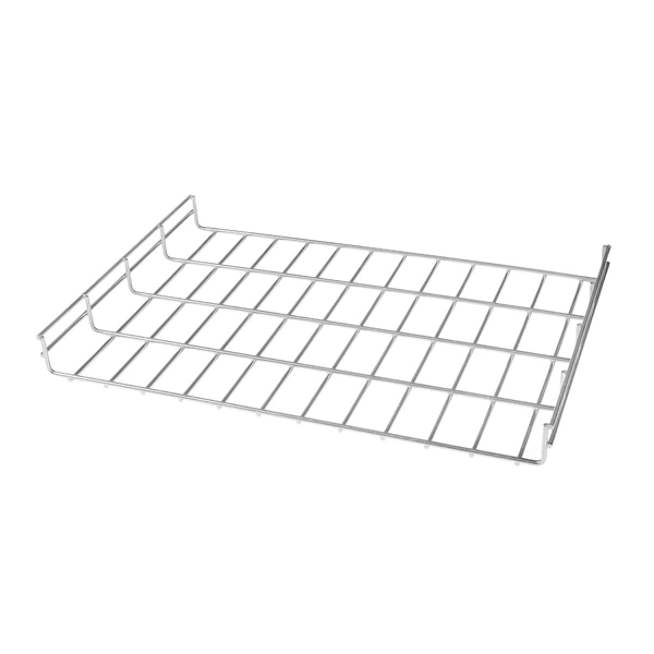
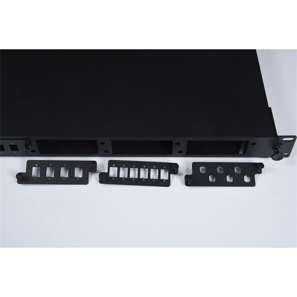
Telecom Racks & Cabinets
19-inch racks, wall-mount cabinets, open frames with high load capacity and seismic rating.
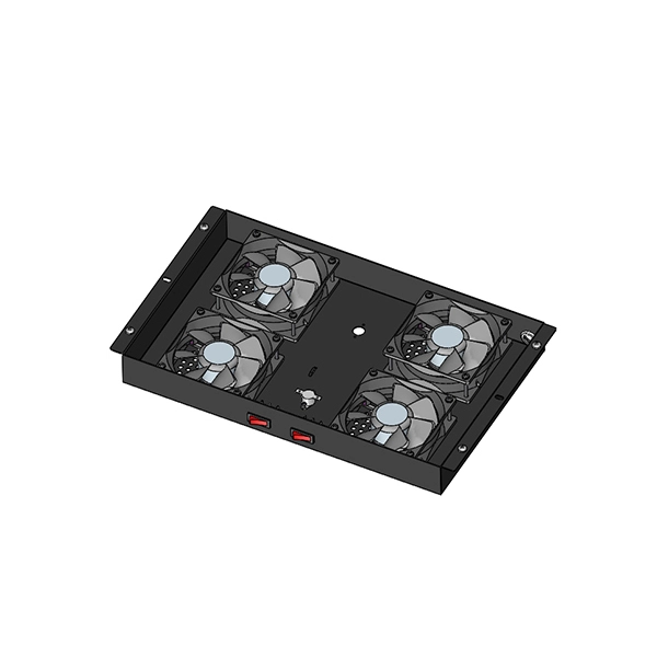
Outdoor Climate Cabinets
IP55/IP66 outdoor enclosures with integrated cooling/heating, -40°C to +55°C operation.
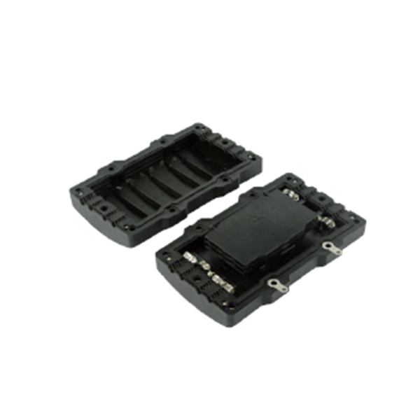
Smart PDUs & Power Distribution
Intelligent PDUs with remote monitoring, per-outlet switching, and environmental sensors.
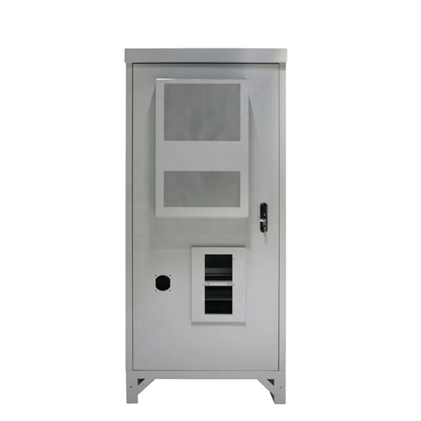
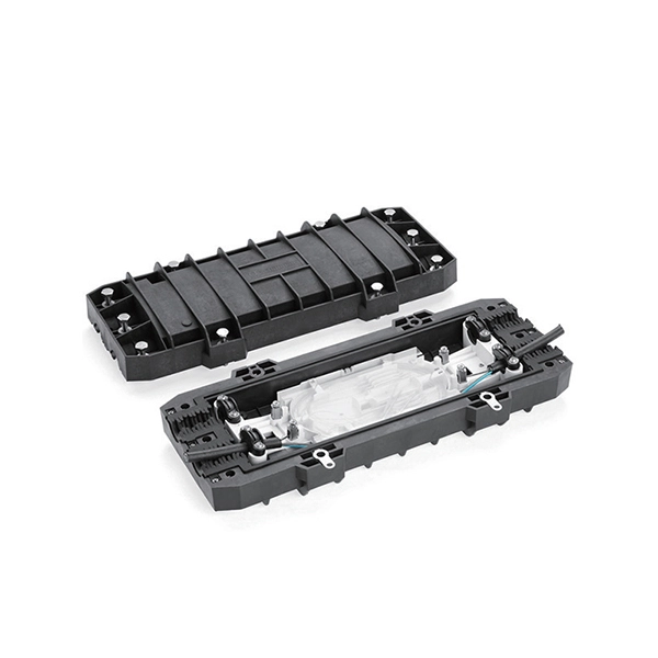
Shelters & Network Cabinets
Prefabricated telecom shelters, emergency comms shelters, and network cabinets with cable management.