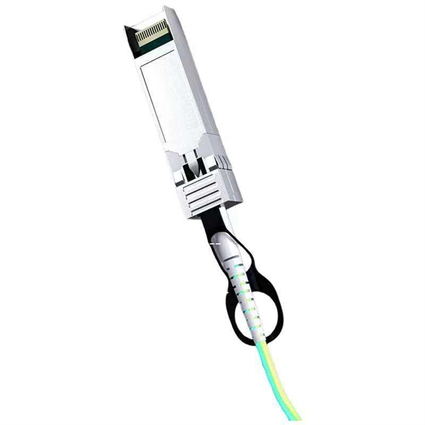
COMNEN 400G QSFP112 DR4 LPO Optical Transceiver Datasheet
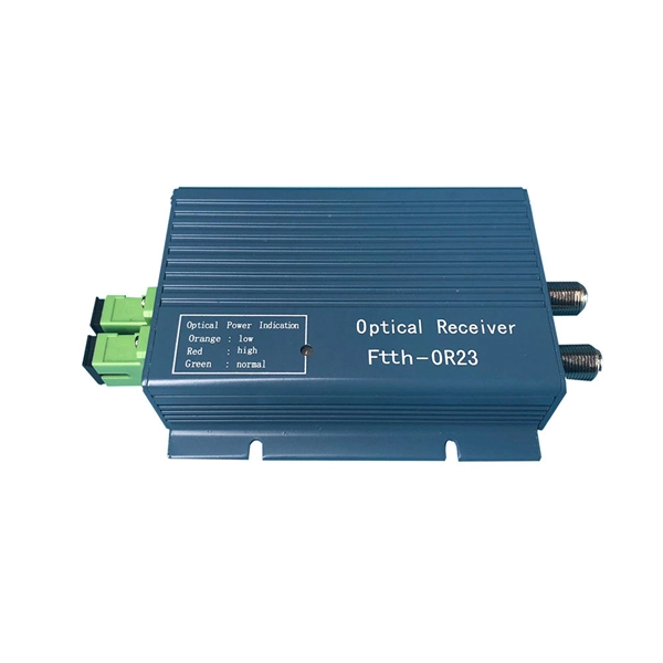
On the receiver side, the module converts 4 channels of parallel optical signals of 100Gb/s each channel for an aggregate data rate of 400Gb/s into 4 channels of 100Gb/s (PAM4) electrical output data. An
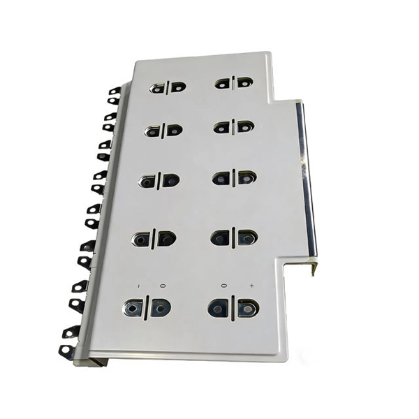
Transmitter/receiver photo IC for optical link
When an optical signal is input to the photodiode, an amplifier converts the current into voltage and amplifies the signal. Then, a comparator converts the signal into CMOS digital output.
Understanding Optical Modules: Working Principles,
Explore the working principles, structures, and performance metrics of optical modules, essential components of optical fiber communication systems. Learn
Understanding Optical Modules: Working Principles, Structures, and
Explore the working principles, structures, and performance metrics of optical modules, essential components of optical fiber communication systems. Learn about key indicators such as average
High Performance Analog Interface and Clock Products
It is typically measured as an rms value and caused by electronic (thermal) or optical noise in the system. Random jitter will increase with increasing system bandwidth and decreasing received
Optical parameters
This guide provides average transmit and receive power ranges for transceiver modules. Transceivers are manufactured to meet the specifications (usually of the IEEE standards) and ranges represent
Understanding Optical Transceiver Modules: A Comprehensive Guide
Transmitter Power Parameters in Optical Transceiver Modules Transmitter (Tx) output is characterized by average power (Pavg), extinction ratio (ER), and optical modulation amplitude (OMA).
Optical Module Working Principle | SFP Transceiver Technical Guide
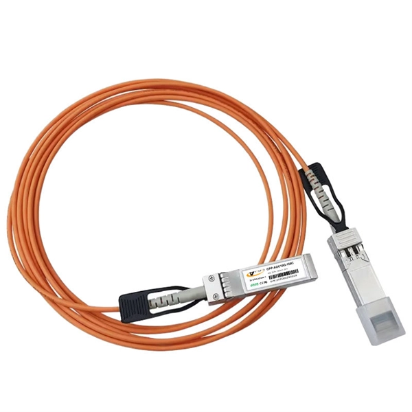
As illustrated in typical SFP internal structure diagrams, the module''s core components include an optical transmitter assembly (TOSA), laser driver, optical receiver assembly (ROSA)—some high
Understanding TOSA, ROSA, and BOSA in Optical
TOSA, ROSA, and BOSA are key components in optical transceivers, enabling high-speed data transmission, reception, and bidirectional
Optical Transmitter and Receiver OI1125 * OI2125
The input voltage range (250 mV to 1.5 V) transmitter and OI2125 O/E receiver offer a simple and cost-effective solution for generat-ing and receiving SONET/SDH compliant opti-cal signals for bit error
The FOA Reference For Fiber Optics
The NIST primary standard for all power measurements is an ECPR, or electrically calibrated pyroelectric radiometer, which measures optical power by comparing the heating power of the light to
CHAPTER 5 OPTICAL SOURCESAND FIBER OPTIC
Must couple sufficient optical power to overcome attenuation in the fiber plus additional connector losses and leave adequate power to drive the detector. Should have a very narrow spectral bandwidth
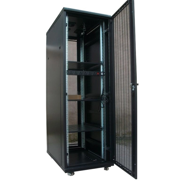
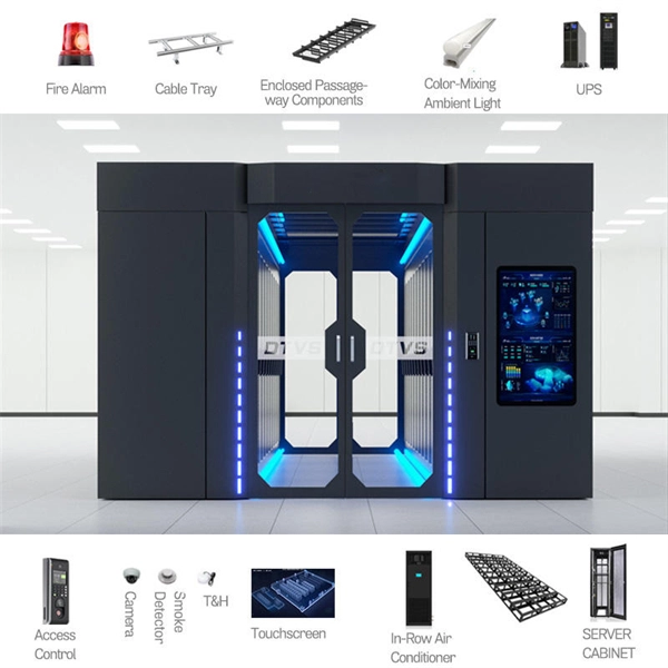
Telecom Racks & Cabinets
19-inch racks, wall-mount cabinets, open frames with high load capacity and seismic rating.
Outdoor Climate Cabinets
IP55/IP66 outdoor enclosures with integrated cooling/heating, -40°C to +55°C operation.
Smart PDUs & Power Distribution
Intelligent PDUs with remote monitoring, per-outlet switching, and environmental sensors.
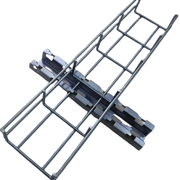
Shelters & Network Cabinets
Prefabricated telecom shelters, emergency comms shelters, and network cabinets with cable management.