-
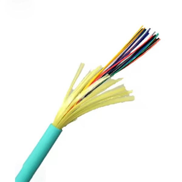
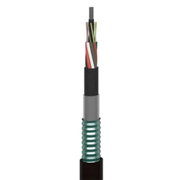
Optical cables are all based on the principle of optical fiber transmission
Fiber optic cables have revolutionized telecommunications, data transmission, and network infrastructure by offering a faster, more reliable means of communication. The core principles behind fiber optic transmission rely on optical technology, enabling the transfer of information. In this article, we will learn about Optical Fiber Light Transmission, Optical fiber light transmission is a technology that enables the transmission of data and information through thin strands of glass or plastic fibers using light signals. To. An optical fiber can be understood as a dielectric waveguide, which operates at optical frequencies. The device or a tube, if bent or if terminated to radiate energy, is called a waveguide, in general. fiber optics, the science of transmitting data, voice, and images by the passage of light through thin, transparent fibers.
[PDF Version]
-
How high a temperature can single-mode optical fiber withstand
The high numerical aperture of these SM optical fibers guarantees low attenuation values even with narrow bending radii and in coils. Single-mode fibers with a carbon, acrylate, or polyimide coating that can withstand the highest stress and temperatures of up to 300°C. Optical fiber's ability to withstand extreme heat and cold directly impacts signal integrity, network reliability, and maintenance costs, especially in harsh environments like industrial facilities, outdoor installations, and data centers. As businesses increasingly rely on robust digital communications, understanding the environmental factors affecting fiber optic cables, particularly. In this work, we analyze the thermal effects occurring in optical fibres, such as the coating heating due to high power propagation in bent fibres and the fibre fuse effect. Thanks to their fluorinated. The working temperature of a standard fiber optic network cable is -40 º C to+75 º C. Please consult the manufacturer for specific information.
[PDF Version]
-
No change in optical fiber sensor light intensity
This function is effective when the intensity value does not change (saturation) from the maximum value of the display-possible range in using the fiber unit at close range. * To disable this function, press. Among the reasons why optical fibers are such an attractive are their low loss, high bandwidth, immunity to electromagnetic interference (EMI), small size, light weight, safety, relatively low cost, low maintenance, etc. At the heart of this technology is the optical fiber itself -- a hair-thin. A fiber optic sensor is a measurement device that uses light traveling through a glass or plastic filament to determine a physical quantity such as temperature, pressure, or strain. These sensors replace traditional electronic sensors by using light waves instead of electrical signals. The optical. Press and hold the and buttons simultaneously for three seconds. Use the to select "rSt", then press the button.
[PDF Version]
-
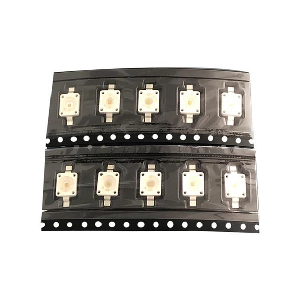
Fiber Optic Sensor M11
Its high power enables use in a wide range of detection applications including: transparent targets, repeated bending, small targets, variable target position. A fiber optic sensor is an instrument that measures light from an LED (or other device) for detection purposes. These devices are most commonly used in factory automation environments. With a diverse team of +100 experts and a strong patent portfolio, Optics11 delivers ultra-sensitive, reliable, and low-power solutions that give operators earlier warnings and more time to act. Enhance. SICK's comprehensive portfolio offers everything you need for high-performance and reliable fiber optic technology. From high-quality fiber-optic amplifiers to rugged optical fiber cables and matching accessories. In combination, these perfectly matched components enable high efficiency and. Many types of industrial switches available: pushbuttons, selector, push pull button, pilot light, illuminated, limit, photoelectric, proximity, relays, circuit breakers and starters.
[PDF Version]
-
Cable and Optical Fiber Survey Report
The report on the fiber optic cable market provides a holistic analysis, market size and forecast, trends, growth drivers, and challenges, as well as vendor analysis covering around 25 vendors. Fiber optic cables are needed for backhaul and fronthaul connectivity because they provide the required bandwidth for 5G base stations and small cell networks. Public cable companies lost 265,000 Internet customers in Q3 2024. 0 will significantly stem this trend. Where Are We Going? to telecom in the past five years (the majority to fiber). Disbursement occurs over multiple years. 19 billion by 2033, expanding at a CAGR of 10. Cable operators plan to carry out a growing number of network upgrades and new builds over the next 5 years, including FTTP-oriented, DAA-oriented, PON-oriented, DOCSIS-oriented, and. The UTC Fiber subcommittee serves as a platform for utility industry professionals and executives to address present and future challenges related to fiber optic networks. I need the full data tables, segment breakdown, and.
[PDF Version]
-
How to calculate the transmission speed of a 4-core optical fiber cable
This calculator determines the bits per second that can be transmitted through a multimode fiber cable, given its bandwidth. Key Parameters: • Center Diameter, Fiber Diameter, Packing Efficiency, Section Count Calculation: Visualization: • Color-coded radial diagram with per-section. RP Fiber Calculator is a highly convenient software for doing various calculations on optical fibers with radially symmetric refractive index profiles. It has an intuitive graphical user interface with tabs for the following purposes: Your browser does not support the video tag. The configuration and results can be exported as PDF. You can also select components to configure connections below and add the field configuration below it. The components will show. A 500 MHz·km fiber can transmit 500 MHz optical signals over 1 kilometer, or 250 MHz over 2 kilometers, demonstrating the inverse relationship between bandwidth and distance. 792 meters per microsecond (µs) or 3.
[PDF Version]
-
Middle East Right Angle Bend Fiber Optic Sensor
● Diffuse reflection sensor type ● Sensing distance 90 mm ● Fiber outer diameter 2. Products listed in this catalog offer the versatility and performance needed for industrial automation applications along with premium availability to help drive supply chain efficiency. SUCH fiber optic sensor features a metal probe head with a nickel-plated. This is a series of fiber optic sensor heads designed to be connected to a fiber optic sensor amplifier. Additional options include those with high environmental. FEBUS Optics is the world reference in DFOS, distributed fiber optic sensing systems (DAS, DTS and DSS), to reduce the environmental impact of human activity, protect people, and optimize production.
[PDF Version]
-
Fiber Optic SPR Sensing Principle
This review compares the two most common configurations of SPR sensors: fiber-based and prism-based SPR sensors. This comprehensive review covers various sensor configurations, geometric shapes, and fiber types, advantages of each in terms of integration. The surface plasmon resonance (SPR) technique has proven indispensable as an optical sensing method owing to its extraordinary sensitivity to changes in refractive index, making it crucial for diagnosis of disease diagnostics, environmental assessment, and pharmaceutical development. Recently, field localization techniques using nanostructures or nanoparticles have been investigated on optical fibers for further sensitivity enhancement and significant. SPR sensors provide promising advantages in the realm of chemical and biological sensing, especially when compared to traditional sensing techniques. Sensitivity, input signal range, precision. This paper reports on the past, present, and future scope of fiber-optic SPR sensors in the field of sensing of different chemical, physical, and biochemical parameters. A detailed mechanism of the SPR technique for sensing purposes has been discussed.
[PDF Version]
-
Inquiry about large-core diameter optical fiber G 652
652 fiber is typically 8-10 microns, with a cladding diameter of 125 microns. The difference in refractive index between the core and cladding allows the light signal to propagate within the core, thereby reducing signal loss. This document outlines the specifications for a single-mode optical fiber and cable designed for use around the 1310 nm zero-dispersion wavelength, suitable for both the 1310 nm and 1550 nm regions, and compatible with analogue and digital transmission. It details the fiber's geometrical, optical. Max. Ideal for cable mounting inside buildings, patchcords and/or i terconnection cables. It offers significant added value in Fibre-to-the-Home (F me splicing machines. A Fiber Reinfor ed Plastic (FRP) locates in the center of core as a non-metallic strength member.
[PDF Version]
-
What is the safe distance for a 10kV optical fiber communication cable
Generally a 12 inch to 24 inch soil separation is recommended as a safety barrier and for locating purposes. IV. Aerial Cable Installation Pathway Separation When placing, installing, or rearranging communication cables and service drops, including optical fiber, copper and coax, the proper clearance requirements must be maintained. When there are two different voltage ratings on cables, separation, either mechanical or by distance, is to avoid an insulation breakdown of the higher rated cable from breaking down the. Abstract:The design, installation, and protection of wire and cable systems in substations are covered in this guide, with the objective of minimizing cable failures and their consequences. There are three main reasons for this: First, high-bandwidth signals are more susceptible to chromatic dispersion than. to n utral comm.
[PDF Version]
-
Minimum Detectable Object by Fiber Optic Sensor
Minimum detectable object is the smallest sized object detectable by the sensor. Fibre units with smaller bend radius are beneficial in locations where routing is difficult. The distance from which the sensor can detect targets. For thrubeam fibre units, this is the size of object that will obstruct the optical axis. Fiber optic proximity sensors are used to detect the proximity of target objects using light. The following mode names and response times apply to the modes given in the Sensing distance column. In addition, positional adjustment of the detection point can be easily performed when mounting thanks to the inclusion of a sleeve and the workpiece not being hidden by the tip even when approaching the.
[PDF Version]
-

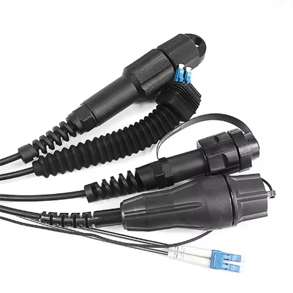
Will the optical fiber distribution box have a BBU
It sits in an enclosure with the Battery Backup Unit (BBU) and associated wiring. It has an optical port connecting to the external Customer Splice Point, an Ethernet port connecting to the communications provider's (CP) router, and a telephony port connecting to the voice. units on towers, buildings, or light posts. The RRU is normally located at the top of a tower, roof, or similar bu lding object and very close to the antenna. On the other end, the. RRU and BBU are crucial components in base station construction, enabling a distributed architecture that improves efficiency and reliability. In a distributed base station. Fiber Optic Distribution Box (FDB) / Fiber access terminal box (FAT) / optical termination box (OTB) / Fiber termination box (FTB) / Optical Distribution box (ODB) are a compact fiber management box used for FTTH application. For more. The enclosure is attached to the wall with 2 screws, instead of the 4 on the previous ONT A template is provided with the unit to ensure correct screw location The enclosure will fit over a double back box to allow the connectorised cable to be inserted through the back of the unit.
[PDF Version]
-
Effect Length of Optical Fiber Communication Technology
Fiber optic cable transmission distance is determined by two primary physical factors that affect signal quality as light travels through the fiber medium. The basic transmission mechanisms of the various types of optical fiber waveguide have been discussed in Chapter 2. The greater the distance, the greater. To meet demand of increase in the telecommunication data transmission. Total internal reflection (critical angle, using Snell's law). Lighter and thinner then copper wire. The cladding's refractive index is slightly smaller than that of the core, which confines light within the core and propagates by repeated total reflection at the boundary with the. An optical fiber, or optical fibre, is a flexible glass or plastic fiber that can transmit light from one end to the other.
[PDF Version]
-
Experiment on the Principle of Fiber Optic Pressure Sensor
In this report, the development, testing, and deployment of a fiber-optic-based extrinsic Fabry-Perot pressure sensor is discussed. Fiber optic pressure sensors use light modulation to measure pressure, offering high sensitivity, EMI immunity, and wide-ranging applications.
[PDF Version]
-
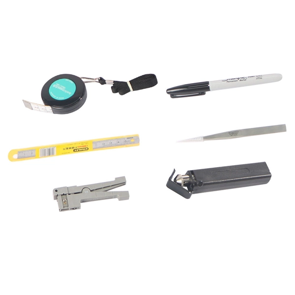
What dB value is considered acceptable for optical fiber splicing
Acceptable splice loss in optical fiber is typically considered to be less than 0. What is the typical acceptable splice loss for single-mode fiber using fusion splicing? What is the acceptable splice loss for multimode fiber using mechanical splicing? How does fiber alignment affect splice loss? Why is cleaning the fiber important before splicing? What role does the cleaver play. Acceptable dB loss for fiber depends on the component you're measuring: a single mated connector pair should lose no more than 0. 5 dB per kilometer depending on the type and wavelength. The total. However, acceptable values depend on: * Project specifications * Link budget calculation * Network type (FTTH vs backbone) * Customer SLA requirements 🛠 Fusion vs Mechanical Splicing * **Fusion splicing** typically gives lower loss (0. * **Mechanical splicing** usually results in. The splice loss is measured in decibels (dB) and is influenced by various factors such as the quality of the splice, the alignment of the fiber cores, and the type of splicing technique used. 5 dB, while for multimode. For each connector, we usually figure 0. However, various factors, such as fibre cleanliness, core.
[PDF Version]
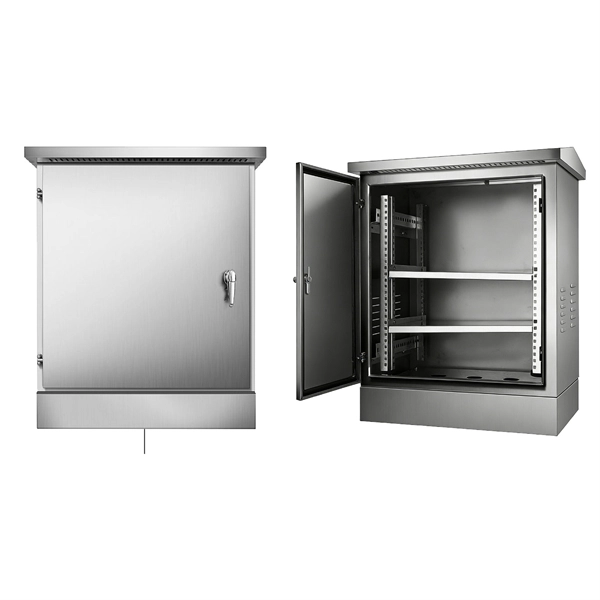
Telecom Racks & Cabinets
19-inch racks, wall-mount cabinets, open frames with high load capacity and seismic rating.
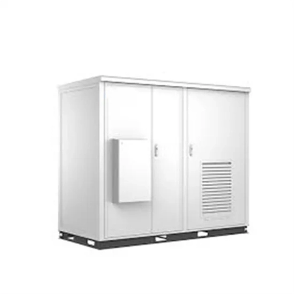
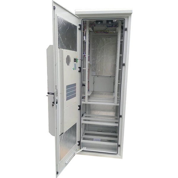
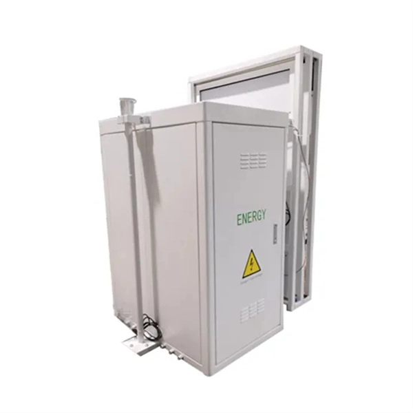
Outdoor Climate Cabinets
IP55/IP66 outdoor enclosures with integrated cooling/heating, -40°C to +55°C operation.
Smart PDUs & Power Distribution
Intelligent PDUs with remote monitoring, per-outlet switching, and environmental sensors.
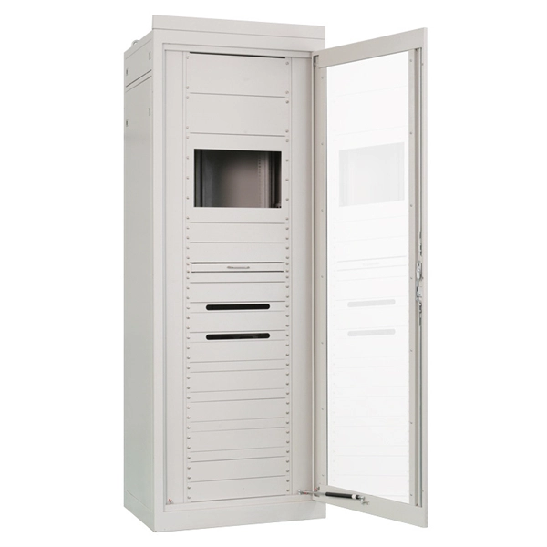
Shelters & Network Cabinets
Prefabricated telecom shelters, emergency comms shelters, and network cabinets with cable management.