-
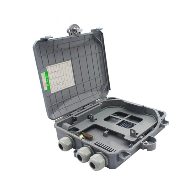
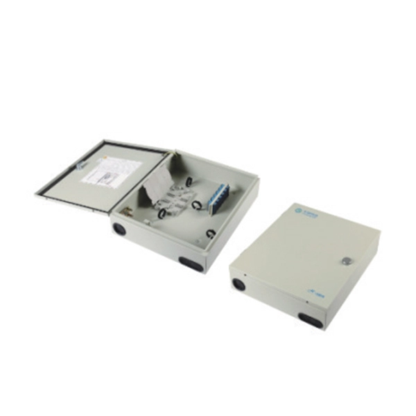
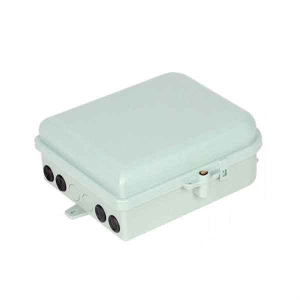
Performance Comparison of High-Density Fiber Distribution Box G 657A1 and Alternative Solutions
This objective technical guide will break down the G. 657A2 comparison, analyzing their physical structures, bend radii, and Mode Field Diameter (MFD) compatibility. Understanding the Fibers: Bend Radius and ApplicationsAs Fiber to the Home (FTTH) networks expand, technicians frequently encounter different fiber standards in the field—most notably ITU-T G. A common question among network engineers is how these fibers differ, especially when it comes to fusion splicing. B3 fibers are widely adopted, each designed for specific applications and environments. This article breaks down the key. Single-mode optical fibers are the backbone of modern fiber optic communication networks, enabling high-speed, long-distance data transmission with low attenuation and high reliability. 657 are. The International Telecommunication Union (ITU-T), a UN agency that formulates standards for telecommunications and information technologies, divides single-mode fibers into six categories of G. 657 standards were developed to address the growing. Fiber Optic Standards Comparison: G.
[PDF Version]
-
How to calculate the loss from cutting a telecommunications fiber optic cable
The loss budget formula adds fiber length, connector/splice losses, and a safety margin (usually 3 dB). • Use worst-case estimates and validate with actual measurements. A tool that computes how many fibers fit in a circular bundle and splits them into user-defined segments for cable-assembly planning. Key Parameters: • Center Diameter, Fiber Diameter, Packing Efficiency, Section Count Calculation: Visualization: • Color-coded radial diagram with per-section. To ensure a fiber optic link operates correctly, you need to calculate its loss, power budget, and power margin. The calculation methods are as follows. In fiber optic cabling, it is often necessary to calculate the maximum loss over a certain length of line. After entering your values, please ensure you click the 'Calculate Link Loss' button at the bottom of the page to generate your total link loss.
[PDF Version]
-
How to calculate the test loss of optical cable connectors
To calculate fiber optic link loss budget: First, determine total fiber attenuation by multiplying distance by attenuation coefficient. Add connector losses (typically 0. To be able to judge whether a fiber optic cable plant is good, one does a insertion loss test with a light source and power meter and compares that to an estimate of what is a reasonable loss for that cable plant. Over 95% of global internet traffic travels through fiber optic cables. At TREND Networks, we are frequently asked how much loss is allowed when conducting testing on fiber optic cabling. Unfortunately, it is not a simple answer and depends on several factors. First, you should be aware of the fiber loss formula: The Total Link Loss = Cable. Use this worksheet to input values for all variables that will impact your system's performance.
[PDF Version]
-
How to calculate the support frame for trough-type cable trays
Cable tray support quantity can be calculated using a simple formula: Support Quantity = Total Length ÷ Support Spacing + 1 20 ÷ 2 + 1 = 11 supports In a typical project, a 20-meter cable tray with 2-meter spacing requires 11 supports. This guide covers the critical steps, from selecting the right electrical cable tray and performing accurate cable fill calculations to managing a safe cable pull through and ensuring all bonding and grounding requirements are met. For licensed electricians, mastering these principles is essential. This article explains the principles, methods, and practical examples for calculating cable tray support quantity. This is a description of how to select, install, and support these metal or plastic frames, on which electrical wires are installed. You don't need a PhD—just a consistent method. List cable types, diameters, and weights per metre.
[PDF Version]
-
How to calculate the quantity of iron components in cable trays
The calculator supports multiple tray sizes (100-600mm), various cable types, and provides detailed formulas for fill ratio, weight estimation, and structural analysis. Tip: Standard mesh configurations are 25×50mm or 50×50mm. Smaller mesh provides better support for smaller. The primary rulebook used in the safe use of cable trays is NEC Article 392. This is a description of how to select, install, and support these metal or plastic frames, on which electrical wires are installed. You should consider it as a series of instructions that make the buildings resistant to. The right cable tray sizing calculator helps engineers turn cable schedules into a verified tray width and fill check before material ordering and site installation. This calculator features an interactive interface with advanced visualizations. Accurate fill ratio analysis and tray sizing per NEC, IEC 60364, and BS 7671 standards. Enter your cable schedule below to get started.
[PDF Version]
-
How to calculate the manufacturing cost of optical modules
This article provides a comprehensive guide on cost analysis for raw materials, offering step-by-step methodologies, best practices, and insights driven by data analytics. Predict fabrication cost, risk and required technologies before production — based on real manufacturing data. PanDao makes these effects visible instantly. variable costs, direct and indirect costs, expected ROI and net present. Designing and manufacturing a photonic integrated circuit (PIC)–based optoelectronic module is a symbiosis of various disciplines, where success lies in bringing PIC design, module architecture, process development, and manufacturing into harmony. This blog series helps PIC designers take a. For large-scale AI data centers deploying thousands of optical modules, total cost of ownership (TCO) analysis becomes critical. Understanding the cost structure of optical transceivers can help customers better understand the factors that form prices and provide a reference for.
[PDF Version]
-
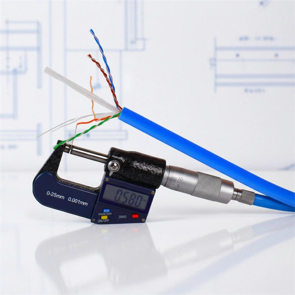
How to calculate the elasticity coefficient of optical cables
See results instantly above the form, then adjust values. All calculations use base-10 logarithms. Used only in measured attenuation mode. The most fundamental parameter for optical fiber is geometry, since the dimensions of the fiber determine its ability to be spliced and terminated to other fibers. The core diameter, cladding diameter and concentricity are the most important factors on how well one can connect or splice two fibers. Estimate peak pull tension, bend drag, and safe working margin before you start the cable pull. Length is needed. The Telecommunications Industry Alliance (TIA) and the Electronics Industry Alliance (EIA) jointly developed the EIA/TIA standard, which specifies the performance and transmission requirements of optical cables and connectors, and is now widely accepted and used in the optical fiber industry.
[PDF Version]
-
How to calculate the wiring requirements for the control cabinet
How do you need to design control circuit wires to comply with UL 508A? The wire size for control cables within the control panel must be a minimum of 18 AWG, with the exception of control cables for PLC inputs/outputs. The conductor cross-section is determined using Table 38. Here's how to approach the design: Before you start designing, it's important to define your requirements. Identify the system needs —what processes or machines will. Designing a truly robust electrical control panel requires adherence to a rigorous, systematic process. Sure, the specs of the wire itself matter (and we'll cover them below), but layout and safety planning are arguably even more important. cUL certification is similar to CSA (Canadian Standards.
[PDF Version]
-
How to calculate fiber optic repeater segments
Repeater count comes from dividing total length by spacing, rounding up so the route has enough segments, and subtracting one because the landing stations at the ends are not counted as in-line repeaters. This calculator provides calculations related to optical amplifiers and repeaters in fiber optic communication systems. Converts canvas coordinates to real distances using the selected. This page provides information about a Fiber Optic Loss calculator and the formulas used in its calculations. Check total loss, power margin, and feasibility clearly. Choose the network family you want to check. Baud Rate (kbit/s) Devices per Segment.
[PDF Version]
-

How to calculate fiber optic splice attenuation
The calculator essentially performs the following calculation: Total Attenuation (dB) = (Attenuation Coefficient * Cable Length) + (Number of Connectors * Connector Loss) + (Number of Splices * Splice Loss)The calculator essentially performs the following calculation: Total Attenuation (dB) = (Attenuation Coefficient * Cable Length) + (Number of Connectors * Connector Loss) + (Number of Splices * Splice Loss)This calculator helps you estimate the total attenuation (signal loss) in a fiber optic cable link. Here are the details and instructions about each field and how they contribute to the calculation: 1. Attenuation Coefficient (dB/km): This value represents the inherent signal loss per kilometer of. Model optical links with practical engineering inputs fast. Review attenuation, splice, connector, and splitter effects. Check total loss, power margin, and feasibility clearly.
[PDF Version]
-
How to calculate the purchase price of a photoelastic modulator
This estimate is based on the information provided in the document, which includes the negotiated price and the 5% discount. As such, Hinds has become a key contributor to a wide range of critical polarization-based measurements. Learn about the Principles of Operation, Unique Features, and Modes of Operation of our. The Hinds Instruments Pem-90 Photoelastic Modulator Systems are an instrument used for modulating or varying (at a fixed frequency) the polarization of a beam of light. PHOTOELASTIC COATINGS (SESA MONOGRAPH ; NO. 3) By Felix Zandman & Salomon Redner Excellent Condition! Quick & Free Delivery in 2-14 days Photoelastic Study of Pressure Vessel.
[PDF Version]
-
How to calculate the impedance value of a 35KV busbar in a power station
This guide explains the engineering logic behind busbar impedance calculation in a practical and readable manner. It covers core theory, design factors, simplified formulas, and examples that reflect real-world power system work. The aim is to provide a clear technical reference that supports. Line impedance consists of resistance (R), inductive reactance (X), and sometimes capacitive reactance (C) components, but typically R and X dominate for overhead and underground lines. The tables below show common. Step-by-step technique which proceeds branch by branch. Busbar Calculations: This calculator uses standard formulas to calculate the resistance, voltage drop, and power loss in a rectangular busbar. Resistivity is. kVA base, IB base current (A) and ZB base impedance (Ω) are given by following equations: Now that the base parameters are defined let's see how the per unit parameters are defined: If the impedance is desired in actual ohms, the following formula can be used: To convert short circuit current to. The paper presents an analytical method for calculating impedances of rectangular bus ducts. The results of resistances and.
[PDF Version]
-
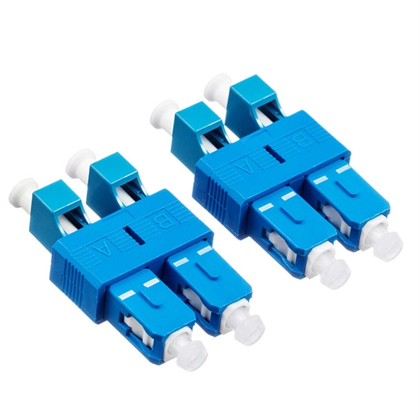
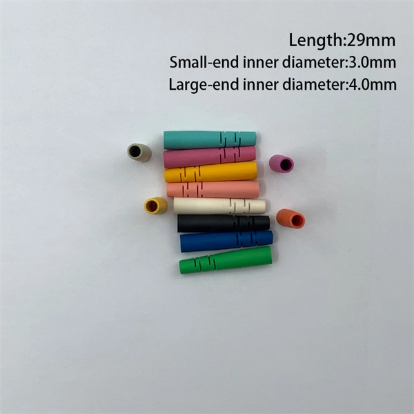
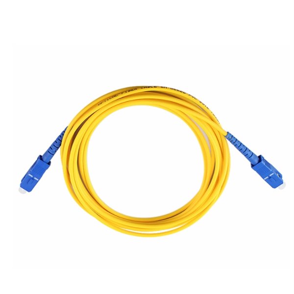
How to tell the front from the back of a fiber optic patch cord
The ferrule end face of the patch cord is ground into different structures. PC, APC, and UPC are three different ferrule polishing methods, representing the structural differences of the front face of the ceramic ferrule. As shown below, the ferrule is the housing for the bare end of an optical. At ZION Communication, we design and manufacture a full range of fiber patch cords for: This guide will help you quickly understand the main types of fiber patch cords and how to choose the right solution for your project – and how ZION can support you with stable quality, flexible customization. Here at Fiber Optic Center, we believe it's important to introduce engineers and technicians to various aspects of the production process to manufacture high-performance, world-class fiber optic cable assemblies. Ideally, your finished fiber optic cable assembly will meet all relevant international. Fiber optic patch cords, also known as fiber optic patch cables or fiber jumpers, are indispensable components in modern optical networks. Fiber optic patch cables are found almost everywhere; cable television networks (CATV), data centers, computer networks, and telephone networks.
[PDF Version]
-
How to calculate the margin of electrical distribution boxes
In today's step-by-step guide, we will demonstrate how to select the right size panelboard (whether it's a load center, distribution board, or circuit breaker panel) according to NEC and IEC standards, with worked examples. Related Post: How to Determine the Right Size Capacity of. Electrical panel design calculations are essential for ensuring safe and efficient power distribution. Unlike standard junction boxes, these distribution systems must. This guide dives deep into the principles, methodologies, and tools required to perform accurate electrical load calculations, ensuring compliance with codes like the National Electrical Code (NEC) and optimizing energy use. What is Electrical Load Calculation? 1. Power Supply is 430V (P-P), 230 (P-N), 50Hz. 6 for Non Continuous Load & 1 for Continuous Load for Each Equipment. Branch Circuit-1: 4 No of 1Phase.
[PDF Version]
-
How to calculate the price of cable trays in Myanmar
Cable tray pricing depends on materials, coatings, size, supplier margins, and order quantity —plus hidden costs like shipping and installation. This guide breaks down everything buyers need to know, from price trends to cost-saving tips. The average cable tray price per meter ranges from $2 to. Volza's Big Data technology scans over 2 billion import shipments on over 20 parameters to Buyers who are a perfect match and most likely to work with you. Cable Trays are important for ensuring the protection of the wiring system and supporting insulated electric cables used for distribution and communication. Ltd is one of the trusted Cable Tray. Jeetmull Jaichandlall (P) Ltd. We believe in building fruitful business partnerships. Suitable for Residential, commercial & Industrial use. Easy and fast installation with minimum labor requirement. Accessories : connectors, joints and earth links. Find verified buyers and sellers of Frp Cable Tray in 180+ countries along with their valid phone numbers and email ids.
[PDF Version]
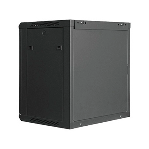
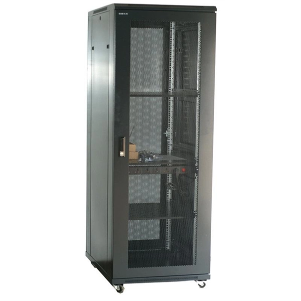
Telecom Racks & Cabinets
19-inch racks, wall-mount cabinets, open frames with high load capacity and seismic rating.
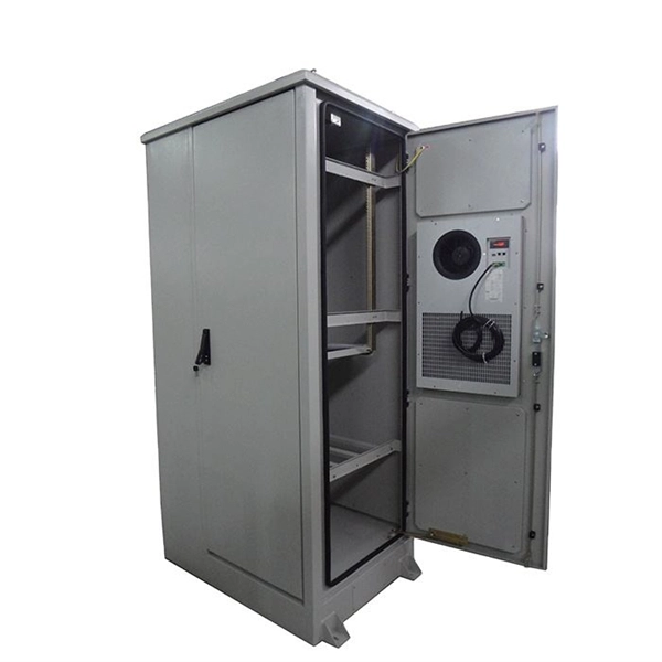
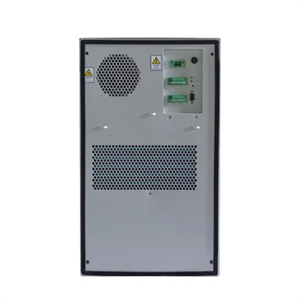
Outdoor Climate Cabinets
IP55/IP66 outdoor enclosures with integrated cooling/heating, -40°C to +55°C operation.
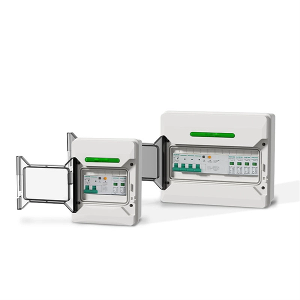
Smart PDUs & Power Distribution
Intelligent PDUs with remote monitoring, per-outlet switching, and environmental sensors.
Shelters & Network Cabinets
Prefabricated telecom shelters, emergency comms shelters, and network cabinets with cable management.