-
Fiber Optic Patch Cord End Face Inspection Techniques
Endface inspection focuses on the visible quality of the polished fiber surface and surrounding ferrule area. You use a fiber microscope or automated inspection scope to check for contamination, pits, chips, cracks, and scratches. Even a small dust particle or scratch on the endface can increase insertion loss, reduce return loss, and introduce random link instability. In FTTH, ODN, and data center environments, you rely on consistent. That is why relying on International Electrotechnical Commission (IEC) industry standards and innovative inspection equipment is the most reliable way to ensure automatic, consistent, and repeatable certification of fiber cleanliness based on specific acceptance criteria. Fiber Contamination, Cleaning and Inspection. This article outlines the specific. 📦 For purchasing, use the RP Photonics Buyer's Guide for fiber endface inspection. It provides an expert-curated supplier directory, buyer-focused technical background information, and structured selection criteria to support professional procurement decisions. Fiber optics is generally quite.
[PDF Version]
-
Fiber optic patch cord end face defects
It's crucial to inspect, clean, and reinspect fiber end faces before mating connectors — whether on patch cords and trunks within the network or on the test reference cord you connect to your tester. In high power transmission, a contaminant may burn and fuse the dirt with the silica material of. Fiber optic inspection microscopes vary in magnification from 30 to 800 power, with 100-400 power being the most widely used range for connector ferrule inspection. In this blog post, we'll take a deep dive into the key performance tests for fiber optic patch cords — polarity verification, insertion loss and return loss measurement, 3D interferometric endface metrology, and endface inspection — along with the relevant standards, equipment, methodologies, and.
[PDF Version]
-
Flame-retardant installation solution for electric cleaning pen on fiber optic end face in Vietnam
Since electrostatic discharge (ESD) is a concern during a 'dry' clean, this kit contain cleaners specifically formulated to dissipate static when the end-face is pulled across a cleaner surface or a stick inserted into an adapter. We offer pre-stocked kits with a variety of cleaning tools and can also build you custom kits to meet your specific application needs. Push-type cleaners feature an. There are four families of fiber optic connector cleaning products that essentially wipe contaminants off the end faces. They can be used in the factory or the field. A fifth family includes electrical bench-top cleaners. The article analyzes contamination sources and their optical impacts, presents detailed tool selection criteria with comparison tables for. Cleaning fiber optic connectors is fast, easy and reliable with our highly engineered solvents, lint-free swabs, precision wipes, and cleaning platforms. It works in three stages: spraying cleaning solution to dissolve contaminants, injecting dust-free gas to dislodge them, and absorbing exhaust and debris.
[PDF Version]
-
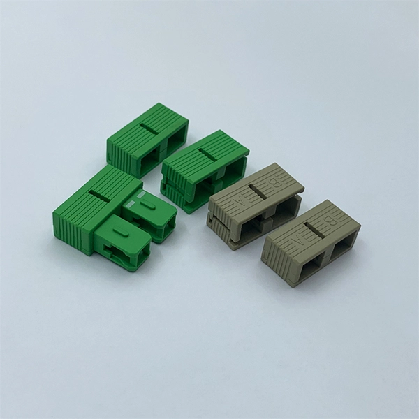
Grade A fiber optic fast connectors at the end face offer good performance
These fiber optic connectors offer terminations without any hassles and require no epoxy, no polishing, no splicing, no heating and can achieve similar excellent transmission parameters as standard polishing and splicing technology. Optical fiber connectors are fundamental components in modern communication networks, ensuring reliable signal transmission. Standards such as IEC 61300-3-47. The differences between optical fiber grades A, B, C, and D primarily pertain to the quality of the fiber end-face, which significantly impacts performance metrics such as insertion loss (IL) and return loss (RL). Selecting the right connectivity requires a clear understanding of fiber end-face types and their compatibility—factors essential to maintaining. It's crucial to inspect, clean, and reinspect fiber end faces before mating connectors — whether on patch cords and trunks within the network or on the test reference cord you connect to your tester.
[PDF Version]
Telecom Racks & Cabinets
19-inch racks, wall-mount cabinets, open frames with high load capacity and seismic rating.
Outdoor Climate Cabinets
IP55/IP66 outdoor enclosures with integrated cooling/heating, -40°C to +55°C operation.
Smart PDUs & Power Distribution
Intelligent PDUs with remote monitoring, per-outlet switching, and environmental sensors.
Shelters & Network Cabinets
Prefabricated telecom shelters, emergency comms shelters, and network cabinets with cable management.