-
Main Inspection Standards for Single-Reel Optical Cables
A practitioner-level walkthrough of the IEC 60794 framework: standard structure, mechanical and environmental test methods, type vs routine testing, common failure modes, and procurement specification guidance. d suppliers of electrical construction services. Existence. Standard for Installing and Testing Fiber Optic Cables AN AMERICAN NATIONAL STANDARD NECA/FOA 301-2016 Standard for Installing and Testing Fiber Optics Published by National Electrical Contractors Association Jointly developed with The Fiber Optic Association T h e F iberO pti c Associat i o n FOA. The International Electrotechnical Commission (IEC) is the leading global organization that prepares and publishes International Standards for all electrical, electronic and related technologies. Please make sure. The Contractor tasked to perform testing or splicing on any fiber optic cable will follow these testing standards to fulfill their contractual obligations.
[PDF Version]
-
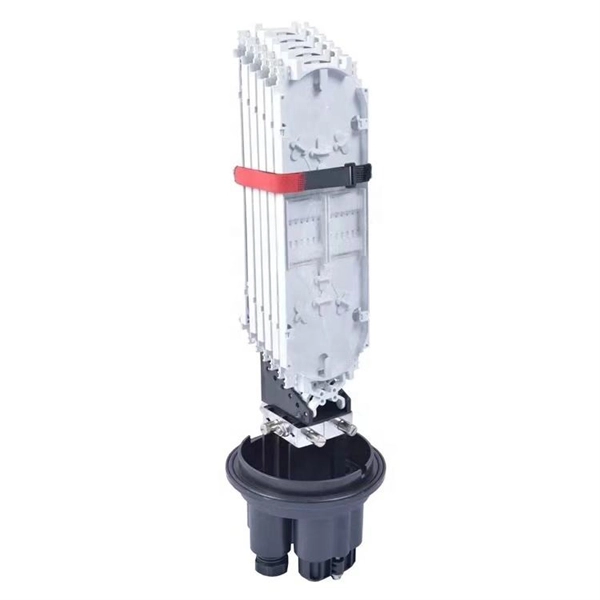
Fiber Optic Splice Box Inspection Report
This template supports fiber optic splicing work by guiding teams through key documentation and quality checks. Record the job details (conducted on, prepared by, location) and the joint name, then capture photographic evidence of strength members, internal splicing across all trays and splitters. All Rights Reserved. fCONSTRUCTION QUALITY REQUIREMENTS FOR FTTP & SSP Work Orders This document provides Construction Technicians, Construction Managers, FTTP/SSP Vendors, and Inspectors with the essential information to ensure a quality build and to successfully pass an Outside Plant Inspection. Inspect the splice enclosure for any damage or defects. Verify that all components are accounted for. 5 dB and prevent costly network outages caused by contaminated connectors. They define a minimum baseline of quality and workmanshi for installing electrical products and systems.
[PDF Version]
-
What kind of inspection batch is required for explosion-proof distribution boxes
In accordance with EN 60079-17 standard are required both an initial inspection and regular periodic checks, or ongoing supervision by trained personnel. This section covers the requirements for electric equipment and wiring in locations that are classified depending on the properties of the flammable vapors, liquids or gases, or combustible dusts or fibers that may be present therein and the likelihood that a flammable or combustible concentration. Explosion-proof and flameproof equipment is essential for safe operation in hazardous (classified) locations where flammable gases, vapors, or combustible dusts may be present. Correctly selected and installed equipment helps prevent ignition of explosive atmospheres while allowing industrial. When inspecting Ex I installations, pay particular attention to the following points:- Connection facilities (including junction boxes) must be clearly identified or labelled to shoe that the circuits are intrinsically safe. Cable glands must be correct for the enclosure they enter. and. It can be effectively applied for periodic testing of electrical equipment used in areas with danger of explosion.
[PDF Version]
-

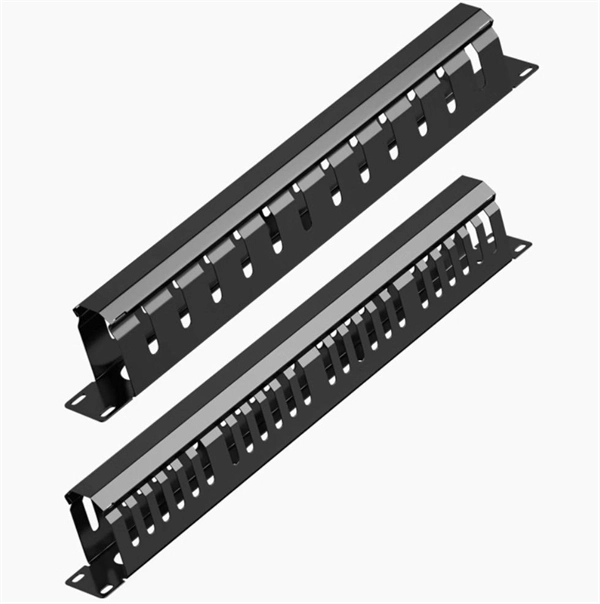
Which inspection batch is the cable tray from
Instrumentation cable trays are critical for organizing and protecting electrical and signal cables in industrial environments. The process described here takes a systematic approach to ensuring that cable tray installations meet safety, reliability, and project-specific needs while following to. The National Electrical Manufacturers Association (NEMA) also publishes three consensus standards that apply to the proper manufacture and installation of cable trays: ANSI/NEMA-VE 1-1998, Metal Cable Tray Systems; NEMA-VE 2-1996, Metal Cable Tray Installation Guidelines; and NEMA-FG-1998. In this detailed guide, we'll explore the essential inspection methods for cable trays, focusing on maintaining their structural integrity, load-bearing capacity, fire resistance, and more. – Vendors supply the required QA/QC documents, tests and certs. Following keywords are used for this topic Inspection Test Plan for Cable Tray and Accessories. Get the Editable Installation Checklists for Cable Trays, Ladders & Conduits with the Full ITP Template to use them at construction sites.
[PDF Version]
-
Dl relay protection inspection cycle
Protective circuit functional testing, including lockout relay testing, must take place immediately upon installation, every 2 years thereafter, and upon any change in wiring. They were talking about doing away with full testing on microprocessor based relays after initial commissioning, relying on the relay's self-test features and metering checks on the relay, and circuit function checks for the equipment being protected. These guidelines should be strictly adhered to during maintenance activities. The maintenance activities for protection relays can be categorized into three main areas:. The purpose of this paper is to provide recommendations for testing SEL relays and guidance for developing a test program.
[PDF Version]
-
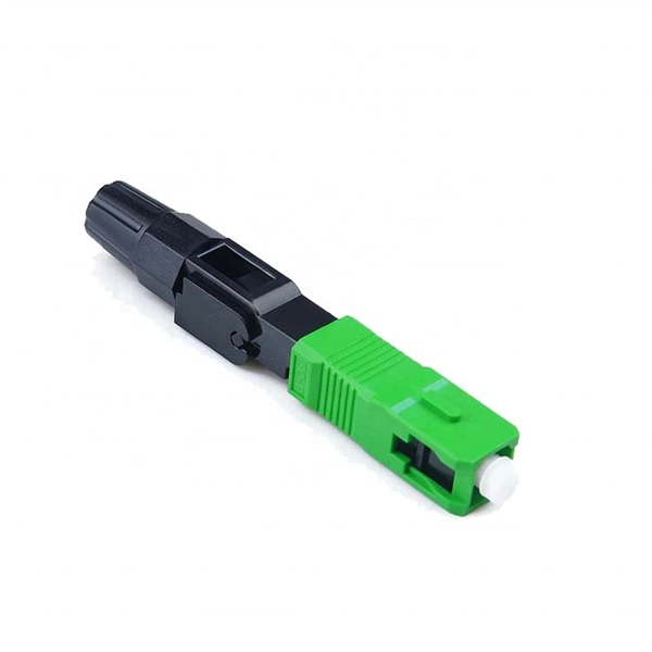
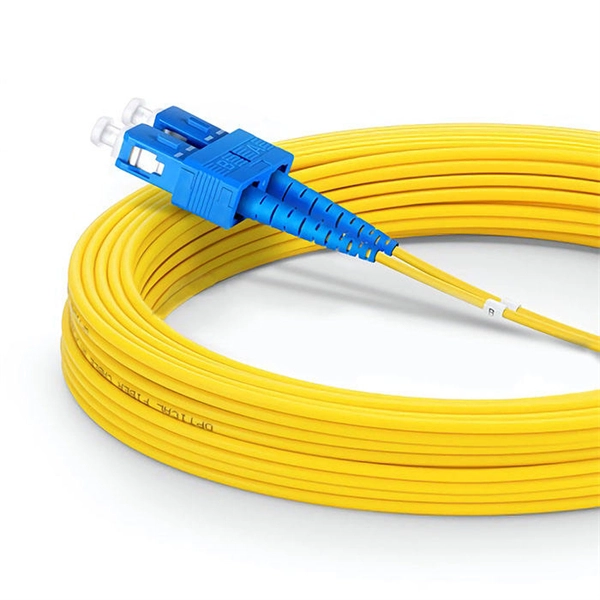
Fiber Optic Patch Cord End Face Inspection Techniques
Endface inspection focuses on the visible quality of the polished fiber surface and surrounding ferrule area. You use a fiber microscope or automated inspection scope to check for contamination, pits, chips, cracks, and scratches. Even a small dust particle or scratch on the endface can increase insertion loss, reduce return loss, and introduce random link instability. In FTTH, ODN, and data center environments, you rely on consistent. That is why relying on International Electrotechnical Commission (IEC) industry standards and innovative inspection equipment is the most reliable way to ensure automatic, consistent, and repeatable certification of fiber cleanliness based on specific acceptance criteria. Fiber Contamination, Cleaning and Inspection. This article outlines the specific. 📦 For purchasing, use the RP Photonics Buyer's Guide for fiber endface inspection. It provides an expert-curated supplier directory, buyer-focused technical background information, and structured selection criteria to support professional procurement decisions. Fiber optics is generally quite.
[PDF Version]
-
Bus trunking and busbar trays
This comprehensive guide compares busbar trunking systems to traditional cable setups, explores the topic of contactor coil voltage (AC vs DC), and helps professionals determine the right choice for their applications. Circuits can be added and removed easily as they are located just above their respective racks. This allows you to make. Busbar systems offer a modern, efficient alternative. EAE Electric started the production and use of busbar trunking.
[PDF Version]
-
How to calculate the impedance value of a 35KV busbar in a power station
This guide explains the engineering logic behind busbar impedance calculation in a practical and readable manner. It covers core theory, design factors, simplified formulas, and examples that reflect real-world power system work. The aim is to provide a clear technical reference that supports. Line impedance consists of resistance (R), inductive reactance (X), and sometimes capacitive reactance (C) components, but typically R and X dominate for overhead and underground lines. The tables below show common. Step-by-step technique which proceeds branch by branch. Busbar Calculations: This calculator uses standard formulas to calculate the resistance, voltage drop, and power loss in a rectangular busbar. Resistivity is. kVA base, IB base current (A) and ZB base impedance (Ω) are given by following equations: Now that the base parameters are defined let's see how the per unit parameters are defined: If the impedance is desired in actual ohms, the following formula can be used: To convert short circuit current to. The paper presents an analytical method for calculating impedances of rectangular bus ducts. The results of resistances and.
[PDF Version]
-
Cambodian Small Busbar Energy-Saving Type
Laminated busbars are essential components in power distribution and electronics systems, offering advantages such as compactness, reliability, and thermal management in Cambodia industrial and renewable energy sectors. Power Busbar Systems are manufactured for the transport and distribution of electrical energy from 32A to 6300A. While IEC62771-1 defines the rating and characteristics, IEC62771-200 defines how this is applied to switchgear. Let's look at four main characteristics: Rated Voltage (Ur): Typically. This is the simplest and most cost-effective setup—a single busbar connects all incoming and outgoing lines. Usage: Commonly found in small substations or setups with limited load requirements. In this blog, I will introduce busbars in detail.
[PDF Version]
-
Bahamas Small Busbar Energy-Saving Installation Solution
LTD specializes in assisting public and private sector clients in designing, installing and retrofitting mechanical and electrical equipment, including renewable technologies, and implementing process improvements that use less energy and improve building comfort. Green Bahamas Co. With over 15 years' experience, we pride ourselves in getting the Job done and done right. Throughout the island of Grand Bahama we have worked on and completed. How Can Busbar Help Reduce Costs? A recent study found that there are roughly 30,000 arc flash incidents in the United States each year, many of which are powerful enough to cause significant injury to workers and costly damage to equipment2. The adoption of busbar power distribution systems on a. "We are the Trusted Experts in the Bahamas, Offering Solutions based on Energy Savings. We Guarantee you a Quick Payback that is Directly Tied to the Real Energy Savings Generated by the Changes we Make. What is a Bus Bar? For the uninitiated, a bus bar is a conductive bar or strip, often made of copper or aluminum, that efficiently distributes electrical power.
[PDF Version]
-
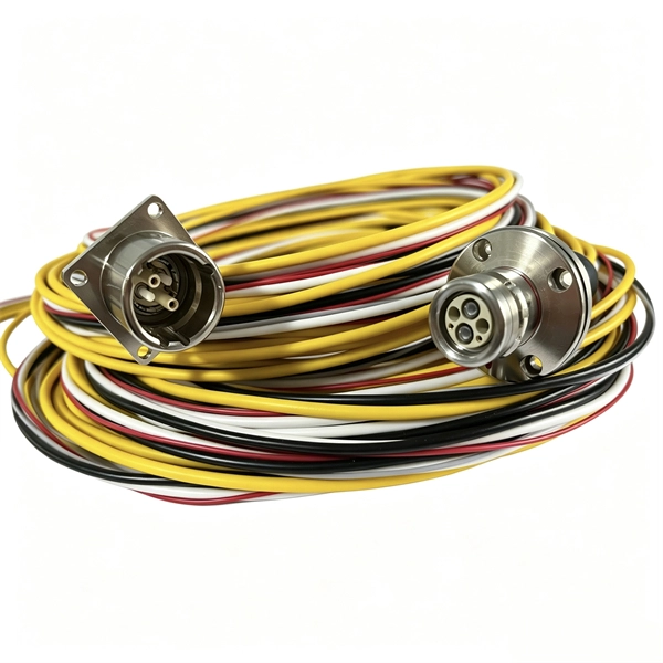
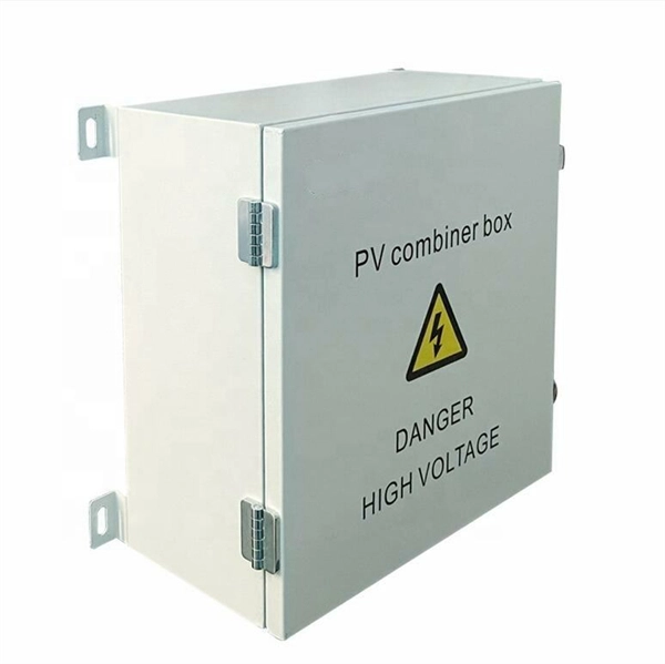
Performance of electrical distribution boxes at construction sites in West Africa
This article examines how modern portable power cabinet system s—such as E-abel distribution boxes paired with industrial waterproof plug connectors —improve temporary power safety on construction sites. Through a real-world project scenario, we explore how structured connectors, IP67 plug systems. Cities such as Lagos, Nigeria, Accra in Ghana, Côte d'Ivoire's Abidjan are expanding in both height and sheer footprint, driven by rising demand for housing, healthcare infrastructure, and commercial spaces. However, there is also fundamental hurdle to cross, how does the industry ensure safety. Power supply on construction sites is crucial to run all the equipment and tools needed to complete a project. Materials and components of proven quality ensure quick and smooth connections and safe supply on site. Unable to find a suitable.
[PDF Version]
-
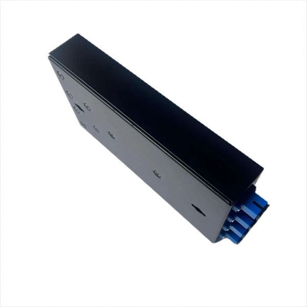
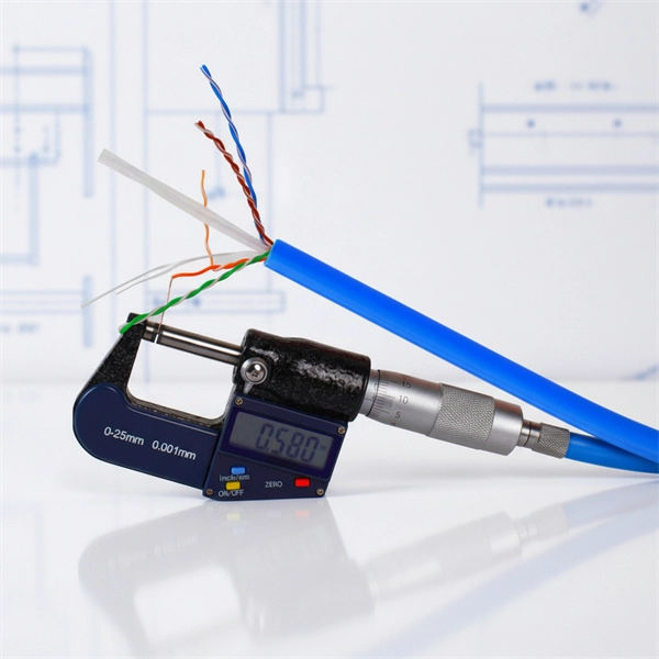
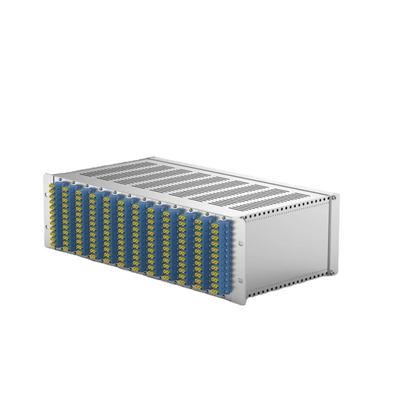
Performance Comparison of 48-core Terminal Box and VS Copper Cable
Copper is cheaper and works great for homes and small offices. This article provides a detailed technical comparison between fiber optic and copper cables, offering a clear perspective for engineers, network architects, and procurement managers. The core distinction between the two technologies lies in the physics of data transmission. Copper cables, a legacy. Fiber core count defines the maximum number of optical terminations or distribution points that a fiber enclosure can support. Selecting the appropriate cable, whether fiber or copper, profoundly impacts your network's. MTP/MPO cables are a class of high-density multi-core fiber optic connectivity solutions widely used in data centers and telecom networks, which are designed to achieve fast connection of multi-core fiber optics through a single interface. Use the interactive scenario selector to find the right medium for your specific network — all processed locally in your browser. PoE Required? Why Fiber: At 50m, fiber optic.
[PDF Version]
-
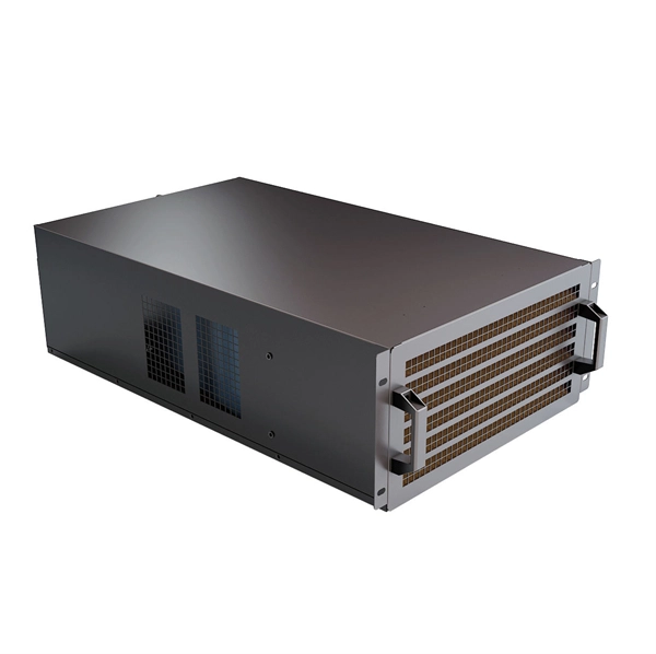
Comparison of High Temperature Resistance of Optical Splitter Boxes and Performance vs Copper Cables
We'll explore thermal limits for different fiber types, explain how temperature affects fiber performance, break down application-specific thermal challenges, and provide actionable tips for choosing the right temperature-resilient fiber. Optical fiber's ability to withstand extreme heat and cold directly impacts signal integrity, network reliability, and maintenance costs, especially in harsh environments like industrial facilities, outdoor installations, and data centers. Laboratory accelerated aging environments have long been used as a measure to predict field performance of optical fiber and cables'. Copper and fiber optic cables each offer distinct advantages and disadvantages that can impact performance, cost, and long-term efficiency. “Copper cables have traditionally served most network links between servers, routers, and switches,” explained. Many engineers struggle with performance drops in high-temperature environments. Harsh heat can degrade normal fiber optic cables, causing downtime, data loss, or expensive replacements.
[PDF Version]
-
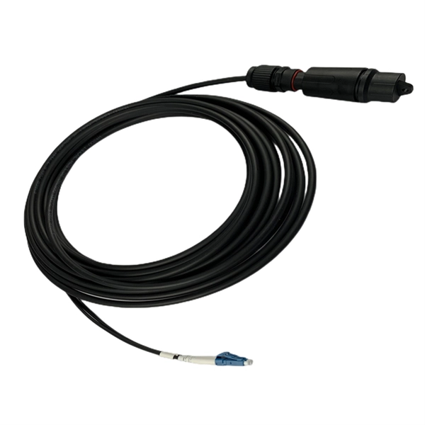
Comparison of Remote Monitoring and Cost-Effectiveness Performance of Fiber Optic Splitters
Therefore, this review paper provides a comprehensive analysis of FTTH PON and AON EC and overviews methods for improving the EE of ONUs and OLTs, as the main elements of FTTH PONs and AONs. In passive optical networks (PONs), optical splitters are essential for distributing signals from a central optical line terminal (OLT) to multiple optical network units (ONUs), enabling efficient fiber-to-the-home (FTTH), fiber-to-the-building (FTTB), and enterprise broadband deployments. Fused. In the rapidly evolving landscape of fiber network deployment, field efficiency and cost-effectiveness are paramount. Traditional testing methods relying on portable equipment and manual labor have long been the standard. The fundamental principle of. With the growing global deployment of Fiber-to-the-Home (FTTH) networks driven by the demand for ensuring high-capacity broadband services, mobile network operators (MNOs) face challenges of excessive energy consumption (EC) of wired optical access networks (OANs). Key areas of focus include innovative maintenance techniques, predictive maintenance through AI and.
[PDF Version]
-
What limits the internal performance of optical modules
Semiconductor material properties determine optical module speed, efficiency, and reliability by affecting bandgap, carrier mobility, and thermal conductivity. It directly translates to faster modulation rates and lower signal distortion. A material with good thermal conductivity dissipates this heat efficiently, preventing. It includes an internal automatic power control circuit (APC) to maintain the stability of the output optical signal power. Receiving Section: Optical signals at a specific data rate are input into the module and are converted into electrical signals by the optical detection diode. This article will systematically analyze the core. With the explosive growth of AI, machine learning, and cloud computing, data-center traffic is rising at an unprecedented rate.
[PDF Version]
Telecom Racks & Cabinets
19-inch racks, wall-mount cabinets, open frames with high load capacity and seismic rating.
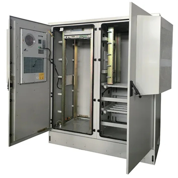
Outdoor Climate Cabinets
IP55/IP66 outdoor enclosures with integrated cooling/heating, -40°C to +55°C operation.
Smart PDUs & Power Distribution
Intelligent PDUs with remote monitoring, per-outlet switching, and environmental sensors.
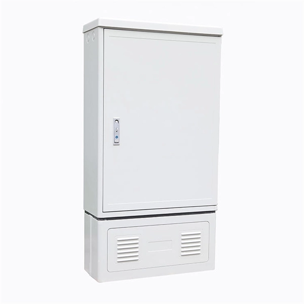
Shelters & Network Cabinets
Prefabricated telecom shelters, emergency comms shelters, and network cabinets with cable management.