-
Grounding wire diameter of indoor cable tray
Single equipment grounding conductors installed in cable trays must be insulated, covered, or bare and sized N° 4 AWG as a minimum, according to Section 392. There is no restriction as to where the cable tray system is installed. The metal in cable trays may be used as the EGC as per the limitations. The Cable Tray Grounding Wire ensures everything runs safely and smoothly. It helps protect equipment from electrical faults, preventing fires and shocks. But, how do you make sure your grounding system works as it should? Let's dive in. What is Cable Tray Grounding Wire? Cable tray grounding wire. Electrical grounding is essential for personal safety and protection against arcing that can occur in any part of the wiring system, motor enclosures, conduits, etc. So when we are talking about sizing EGCs, we mean wire-type EGCs. Per CEC 10-114, the grounding wire must be 6 AWG or bigger.
[PDF Version]
-
Calculation of distance from cable tray bend to wall
Calculate horizontal, vertical, or compound cable tray offsets based on bend angle, offset distance, and available installation space. Measure this distance along the straight tray. Two Bends Per Offset: Every offset requires two equal bends — one to move laterally and one to return to parallel. The total tray section consumed = 2 × single bend length. Pre-fab vs Field Bent: For standard offsets (6, 12, 18 in at 45°), use manufacturer pre-fabricated offset fittings to save. When installing two cable trays in parallel at the same height, the distance between them should be no less than 0. This spacing is crucial for adequate maintenance access, ease of inspection, and ensuring proper airflow for effective heat dissipation. ) that matches or exceeds this value. 8 (Other Mechanical Stresses (AJ)) in that document provides requirements for cable support. IEC 61537 covers cable tray and cable ladder systems for the support and accommodation of cables, while NEC Article 392 governs cable.
[PDF Version]
-
Cable tray support pull-out calculation
Cable tray support quantity can be calculated using a simple formula: Support Quantity = Total Length ÷ Support Spacing + 1 20 ÷ 2 + 1 = 11 supports In a typical project, a 20-meter cable tray with 2-meter spacing requires 11 supports. Helps determine the proper wire size for an electrical circuit based on the voltage drop and current carrying capacity of an electrical circuit. Follow these simple steps: Define Tray Dimensions: Enter the width and depth of your planned cable tray (in mm or inches). Select Fill. Cable Information: Location: Engineer: #/Cond. Sum Area (in^2) Comments Maximum allowable tray fill per Area (in^2) Tray Design Depth = Sum of OD (in) Total Cross Sectional Areas of all cables: Total Sum of the Diameters: in. The right cable tray sizing calculator helps engineers turn cable schedules into a verified tray width and fill check before material ordering and site installation. Open the full calculator for the best experience.
[PDF Version]
-
Calculation of cable bending degree inside cable tray
Calculate the minimum required bend radius by multiplying the cable's outside diameter by its bending factor (e. Then, select a standard tray fitting (300mm, 450mm, etc. ) that matches or exceeds this value. 2” then this cable can be puled without the need of a 90-Deg elbow. Here's a snip of some aluminum, horizontal bend options from Eaton's B-line catalog. I. Would someone kindly let me know the formula to create a flat 45 in say 100 mm cable tray for example. There are 4 factors that influence the. The right cable tray sizing calculator helps engineers turn cable schedules into a verified tray width and fill check before material ordering and site installation. IEC 61537 covers cable tray and cable ladder systems for the support and accommodation of cables, while NEC Article 392 governs cable. Fiberglass cable tray 90 degree vertical inside bend assembly submittal Powering Business Worldwide WIDTH NOMINAL RAIL HEIGHT 90° NOMINAL RADIUS 4 F - 18 - 90 VI 12 NOMINAL RAIL HEIGHT 3 (2" CABLE FILL) 4 (3" CABLE FILL) 6 (5" CABLE FILL) 8 (7" CABLE FILL) MATERIAL F = POLYESTER FV = VINYLESTER FA.
[PDF Version]
-
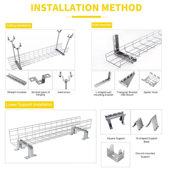
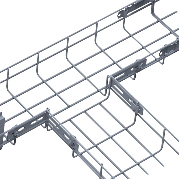
How to install a wire mesh cable tray machine
Whether you're working on an industrial, commercial, or data center project, this step-by-step guide will help you get it done safely and efficiently. 🔧 What You'll Learn: Preparing the installation area and measuring for accuracy Installing mounting brackets and ensuring proper. Wire mesh cable trays provide an excellent solution for managing and organizing cables efficiently. In this complete installation guide, we'll walk you through the process of installing wire mesh cable trays step-by-step, complete with images to illustrate each stage What is a Wire Mesh Cable Tray?In this video, we'll walk you through the entire process of installing a wire mesh cable tray system, from preparation to completion. 🔧 What You'll. For detailed information about the product, please visit our website: https://link. Qualified field personnel working to a. en completely installed, without damage either to conductors or structural system use maintain spacing or to keep cables in place when the tray is ect the minimum bend ra-dius for cables as they exit the bottom of the cable tray. A rung spacing of 6 to 9 inches (150 to 230 mm) is preferable when.
[PDF Version]
-

Calculation formula for cable tray supports in factory buildings
Cable tray support quantity can be calculated using a simple formula: Support Quantity = Total Length ÷ Support Spacing + 1 20 ÷ 2 + 1 = 11 supports In a typical project, a 20-meter cable tray with 2-meter spacing requires 11 supports. As a key structure supporting the cable tray, the accurate calculation of the support quantity directly affects construction costs, efficiency, and safety. In complex engineering environments, the. Stop Costly Cable Tray Installation Errors Now: Avoiding Mistakes in Instrumentation Cable Tray Installation: A Guide for EPC Projects Cable tray sizing in real EPC projects is not limited to simple area calculation. Formula 1: Cable Tray Fill Ratio Where: Total Cable Area (mm²) = Sum of.
[PDF Version]
-
What kind of wire is the cable next to the cable tray
Tray cable is a widely used type of multiconductor or multipair cable approved for installation in cable raceways and cable trays. To that end this Bulletin is intended to discuss the types of cables most frequently used in cable trays and the wiring methods permitted in cable trays under the National Electric Code (NEC) NFPA 70. It is the standard wiring method for industrial plants, commercial buildings, and utility installations where cable trays provide accessible. Cable tray is one of the most common methods of supporting wire and cable. There are many different types of cable tray including basket, ladder and solid-bottom.
[PDF Version]
-
Complete Guide to Cable Tray Accessories in Ghana
Homebase Ventures | Ghana's largest Catalogue of Electrical Supplies. Cable tray end accessories in much quantity for supply selling at affordable prices!! Call for profomas and sample pictures for supply now050XXXXXXX Jiji. The main types of accessories are categorized by their function: Fittings change the path or size of the run, including Elbows (for horizontal or vertical direction. We supply only certified electrical products! Ramdev Steel Industries – Your One-Stop Solution to Get Cable Tray Accessories! Ramdev Steel Industries is experienced in cable tray accessories. Browse our wide selection of.
[PDF Version]
-
Cable tray foundation calculation
Calculate cable tray fill ratio, weight loading, and derating factors for multi-standard compliance. This calculator features an interactive interface with advanced visualizations. Follow these simple steps: Define Tray Dimensions: Enter the width and depth of your planned cable tray (in mm or inches). IEC 61537 covers cable tray and cable ladder systems for the support and accommodation of cables, while NEC Article 392 governs cable. Our cable tray fill calculator is designers to compute the appropriate size and capacity of cable trays. Sum Area (in^2) Comments Maximum allowable tray fill per Area (in^2) Tray Design Depth = Sum of OD (in) Total Cross Sectional Areas of all cables: Total Sum of the Diameters: in. Cable management is the unsung hero of modern infrastructure. Whether you are running heavy copper for a UPS Backup System or delicate fiber optics for a CCTV Security Network, the physical.
[PDF Version]
-
Lao Customized Cable Tray Manufacturer
With over 20 years of expertise, we specialize in the R&D, production, and global supply of high-quality cable tray systems, including perforated trays, cable ladders, trunking, strut channels, and fittings. With non-slip treaded covers to optimize slip resistance, the BKRS Walkable Cable Tray ensures your cables get the best defense. They provide reliability, ease of installation, and cost savings both initially and. Custom manufacturer of cabletrays made from aluminum, fiberglass reinforced plastic (FRP), galvanized and stainless steel materials. Suitable for supporting insulated electrical cables., Ltd (JLH Electric or JLH Cable Tray) has been dedicated to supplying complete line of cable tray solution to worldwide customers for 15+ years. JLH cable trays mainly include cable trunking, cable ladder. Shandong Tianhong Electric Power Technology Co. is a leading cable tray manufacturer in China, founded in 2006. Factory direct supply with.
[PDF Version]
-
Greece Energy-Saving Cable Tray Quotation
Please complete the form below to request a Cable Tray quote. -- Please Select -- United States Afghanistan Åland Islands Albania Algeria American Samoa Andorra Angola Anguilla Antarctica Antigua and Barbuda Argentina Armenia Aruba Australia Austria Azerbaijan Bahamas Bahrain Bangladesh Barbados. The Greek cable trays market is navigating a period of significant transformation, shaped by the dual forces of ambitious national infrastructure modernization and the accelerating energy transition. As of the 2026 analysis, the market is characterized by robust demand stemming from major public. We, one of the reliable PVC Cable Tray Manufacturers in Greece, offer high-quality PVC cable trays, a cost-effective and easy solution for organizing and protecting your electrical cables. Since we are loaded with the right resources, we have been involved in offering our products in a comprehensive range in order to meet the requirements of the different.
[PDF Version]
-
Advantages of Cable Tray Repair
Safety: Prevents overheating and reduces fire hazards. Cost-Effective: Reduces labor and long-term maintenance costs. Cable trays are versatile and used in multiple. Cable trays not only organize and protect cables but also contribute to the long-term efficiency and safety of buildings, factories, and communication networks. Suppose that they are a robust bridge or a shelf, which is developed with electrical cords in mind. The cable trays do not build the wires in the thick pipes but rather leave them out in the open so that they can be seen and. Advantages and disadvantages of using cable tray: easy installation, ventilation, cost-effective, limited load capacity. Disadvantages: Heavy weight, prone to corrosion. Related Articles: Complete Guide to Metal Cable Tray Materials in Industrial Applications 8.
[PDF Version]
-
How many meters of cable tray plus support
Cable tray support quantity can be calculated using a simple formula: Support Quantity = Total Length ÷ Support Spacing + 1 20 ÷ 2 + 1 = 11 supports In a typical project, a 20-meter cable tray with 2-meter spacing requires 11 supports. This calculator determines the maximum number of cables that can be safely housed within a cable tray based on its dimensions and the cross-sectional area of the cables. Cable tray supports are components used to fix and support. IEC 61537 and IEC 60364 require evaluating tray dimensions based on cable quantity, type, and layout configuration. Below are industry-standard tray and ladder dimensions used globally, based on typical installations and in alignment with IEC 61537:2016 and manufacturer catalogs. IEC 61537 covers cable tray and cable ladder systems for the support and accommodation of cables, while NEC Article 392 governs cable.
[PDF Version]
-
What else is polyurethane cable tray called
Wire mesh cable trays, also known as basket trays, are lightweight and provide excellent ventilation, making them perfect for IT and telecommunication setups. Promotes optimal airflow, preventing overheating of cables. Lightweight design ensures easy installation and handling. Unlike conduit systems, cable trays allow cables to be laid in bundles, improving accessibility, heat. This is where cable trays come in, and specifically, we are going to look at Polyurethane Cable Trays. We know you want clear answers about whether these trays are right for your project. A cable. What is a Cable Tray System? A cable tray system is a unit assembly of sections and fittings that forms a rigid structural system used to securely fasten or support cables and wiring. They are widely used across industries such as construction, manufacturing, data centers, and more.
[PDF Version]
-
Calculation of Optical Cable Length for Power Collection Lines
All lengths are calculated in a base unit, then converted. Reel count is ceil (Total ÷ ReelSize), and the rounded order length equals Reels × ReelSize. The Fiber Collimator Calculator helps determine optimal parameters, including lens focal length and beam diameter, for specific fiber types and wavelengths. Export results to share with your field team quickly. Use segments to model conduit, tray, or underground runs. Covers bends, offsets, and path. In this paper, the optimal fiber length in optical ground wire (OPGW) cable during pro-duction process is determined. The results show that in OPGW cable, if the fiber strand-ing length is less than the maximum lay length, the ultimate tensile stress (UTS) percent-age decreases, but if it is. Telcordia and TIA allow a 0.
[PDF Version]
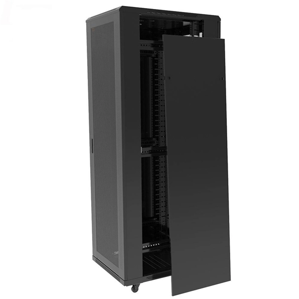
Telecom Racks & Cabinets
19-inch racks, wall-mount cabinets, open frames with high load capacity and seismic rating.
Outdoor Climate Cabinets
IP55/IP66 outdoor enclosures with integrated cooling/heating, -40°C to +55°C operation.
Smart PDUs & Power Distribution
Intelligent PDUs with remote monitoring, per-outlet switching, and environmental sensors.
Shelters & Network Cabinets
Prefabricated telecom shelters, emergency comms shelters, and network cabinets with cable management.