-
How many kilometers of optical fiber cable are considered a backbone
Collectively, these fiber-optic systems stretch approximately 1. 5 million kilometre along the seabed, forming the backbone of global digital connectivity. As of early 2025, an estimated 570 active submarine cable systems span the world's oceans, with roughly 80 additional networks either under construction or in advanced planning stages. The Internet backbone is the principal data routes between large, strategically interconnected computer networks and core routers of the Internet. The fiber backbone carries enormous volumes of data. A total of 1,031 km of fiber optic cable has been installed across five routes: Arlit–Assamaka–Algerian border (220 km), Diffa–N'Guigmi–Chadian border (186 km), Zinder–Magaria–Nigerian border (117 km), Niamey–Dosso–Gaya–Benin border (300 km), and Niamey–Makalondi–Burkina Faso border (118 km).
[PDF Version]
-
The function of cable and optical fiber cable delivery reel
The core function of a fiber optic cable reel is to facilitate the proper unwinding and spooling of fiber optic cable during installation. This is a delicate process that requires attention to detail. These devices are essential for coiling long, continuous materials such as cables, wires, paper, and. The reels are designed for handling fiber cables in temporary installations. It can be stacked, has room on the inside for storing connectors (size up to Probeam Sr. Whether for temporary setups or permanent installations, our selection of cable.
[PDF Version]
-
Crystalline Silicon for Optical Fiber Communication
Silicon-core fibres have unlocked new regimes of mid-infrared transmission, on-fibre Raman amplification and nonlinear wavelength conversion, finding relevance in gas sensing, biomedical diagnostics, high-power laser delivery and all-optical signal processing. Silicon-core optical fibres represent a convergence of semiconductor photonics and conventional fibre technology, embedding a crystalline silicon or silicon–germanium alloy core within a glass cladding. This architecture combines the high refractive index contrast and pronounced nonlinear response. Polycrystalline silicon core optical fibers have been fabricated by modified thermal annealing of amorphous silicon chemically deposited at high pressure. The resulting fibers have small-diameter cores, a geometry advantageous for optical guidance. Moreover, the combination of chemical deposition. Novel core fibers have a wide range of applications in optics, as sources, detectors and nonlinear response media. Optoelectronic, and even electronic device applications are now possible, due to the introduction of methods for drawing fibres with a semiconductor core. Here we explore the underlying.
[PDF Version]
-
The Role of Fiber Core in Optical Cable Splicing
At its core, fiber optic splicing involves joining two pieces of fiber optic cable to ensure that light pulses travel without disruption. This is achieved through fusion splicing or mechanical splices, each offering distinct advantages depending on the project requirements. The goal is to align the microscopic glass cores (typically. In this guide, you will find a chronological description of the fusion splicing process, the principal technical standards, and answers to the real-life questions network engineers and procurement teams may have. Professionals in telecommunications, data centers, and network infrastructure must understand the core functions and why they are fundamental to their fiber optic. The cladding is usually 125 microns in diameter and is uniform across most fiber types. Typically it is stripped away during preparation for fusion splicing. Ensure Your Splicing Tools are Clean – #2.
[PDF Version]
-
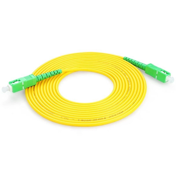
How to make a cold joint for double-wire optical fiber
In this video, we will learn how to joint two Fiber Optic Cables together or Fiber Optic Cable splicing #fiber #fibercable #fiberlaser #fibersplicing #fiberc. Fiber optic joints or terminations are made two ways: 1) splices which create a permanent joint between the two fibers or 2) connectors that mate two fibers to create a temporary joint and/or connect the fiber to a piece of network gear. Either joining method must have three primary characteristics. It is used to connect optical fiber or optical fiber butt pigtail, which is equivalent to making a joint (fiber butt pigtail refers to the butt joint of the fiber core of the optical fiber and the pigtail instead of the pigtail head mentioned in the former), and is used for this kind of cold. At the heart of any robust fiber optic network lies a crucial process: Preparing a fiber cable for termination of a connector or splice. Two types of splices are used in fiber optic cabling one is Mechanical the other is Fusion. What is Fiber Optic Splicing and Why is it Needed? – #1.
[PDF Version]
-
Source manufacturer of optical fiber cables for communication in Democratic Republic of Congo
Genew Technologies and Zhongshi Wosen, both Chinese companies, will help the Democratic Republic of Congo (DRC) build its fiber optic network. Our vision is to become the leading solution provider in Fiber Optic communication system by providing Leading Brands and 'state of the art' services. Its main product is the internet for professionals. Having therefore. The Democratic Republic of Congo (DRC) is poised for a significant boost in its digital infrastructure following the signing of a Memorandum of Understanding (MoU) between the Congolese Optical Fiber Company (SOCOF) and the Agency for Steering, Coordination and Monitoring of Collaboration. SOCOF is a one-person limited company in which the Congolese State is the sole shareholder. It is governed by the Uniform Act revised on January 30, 2014 relating to the law of Commercial Companies and Economic Interest Grouping and by all other laws and regulations in force in the DRC, not.
[PDF Version]
-
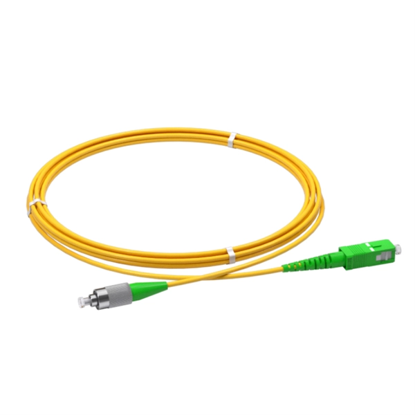
How to connect a single-mode dual-core optical fiber
This guide will break down the professional methods to achieve seamless single-mode to multi-mode conversion, ensuring your network integrity and performance. 📝 Why Can't You Directly Connect SMF and MMF? At its heart, the incompatibility is physical. A fiber media converter takes an Ethernet signal on copper (RJ-45) and converts it to an optical signal on fiber, or vice versa. Single mode light travels in the Ø9 µm core of the fiber, while multimode light propagates in the Ø105 µm inner "1 st cladding". How do we choose, and what are their differences and advantages? Let's learn about this! What is a Single-Fiber (BiDi) Transceiver? Single fiber module also called BiDi transceiver or WDM module.
[PDF Version]
-
Belarusian large-core optical fiber 1310nm
In this article, we explore the key characteristics, common applications, and important comparisons related to 1310nm optical modules. Used for medium-distance links in city networks. As part of the O-band (1260–1360 nm), it balances low dispersion, stable performance, and cost efficiency. This makes it widely adopted in data centers, enterprise backbones, and metro access. The product features an SFP+ package with an LC connector, a 1310nm DFB laser with a PIN photodetector, and supports up to 20km transmission on SMF with power dissipation under 1W. Or It is also suited for analog fiber transmission. Pricing (USD) Filter the results in the table by unit price based on your quantity. A. 10GBASE-LRM SFP+ Transceiver Module 1310nm 220m - FS. com FS United StatesFREE SHIPPING on Orders Over US$79 Contact Us United States / $ USD Sign in Sign up Search Recent Searches Change FREE SHIPPING on Orders Over US$79 United States HomeOptical Transceivers10/25/40/100G. SFP+, 1310nm, LR SMF 10km, 10G DDM, Corning 1LAN-SFPP-10GB-LR Compatible Integra manufactures the highest quality SFPP transceivers in the industry, designed to be 100% interoperable with all OEM platforms.
[PDF Version]
-
What is optical fiber multiplexing equipment
Fiber optic multiplexers are simple but advanced devices that have transformed how audio-video (AV) signals are transmitted, offering unparalleled advantages in terms of bandwidth, signal quality, and efficiency. Optical multiplexing has been a cornerstone technology in the evolution of optical networks, enabling the efficient transmission of multiple signals over a single optical fiber. This article explores how these devices work, their significant role in modern. WDM allows two or more signals to be combined (multiplexed) on a single fiber by using different wavelengths for each signal. Understanding WDM: Ideal for L-Band HTS and Reference or Tx/Rx in a single fiber, in satcom and diverse antennas within broadcast applications. This allows multiple channels of data to be transmitted simultaneously.
[PDF Version]
-
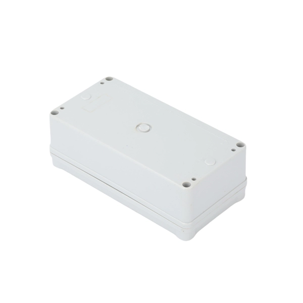
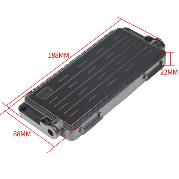
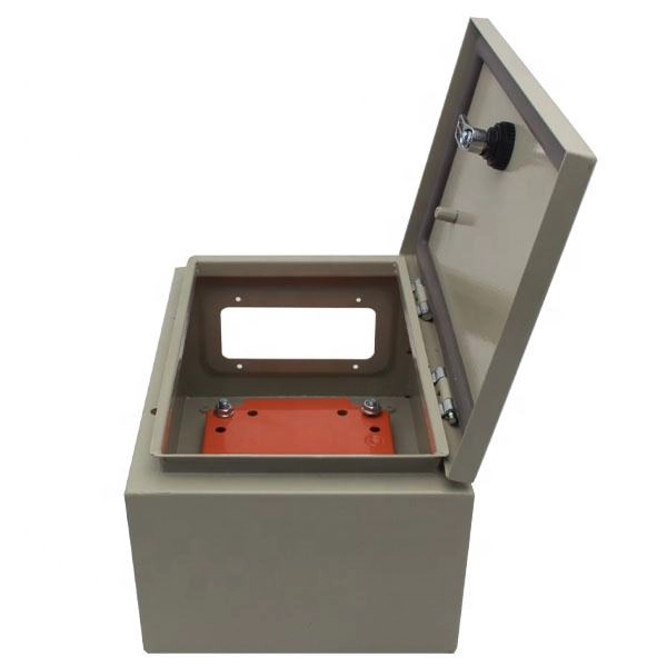
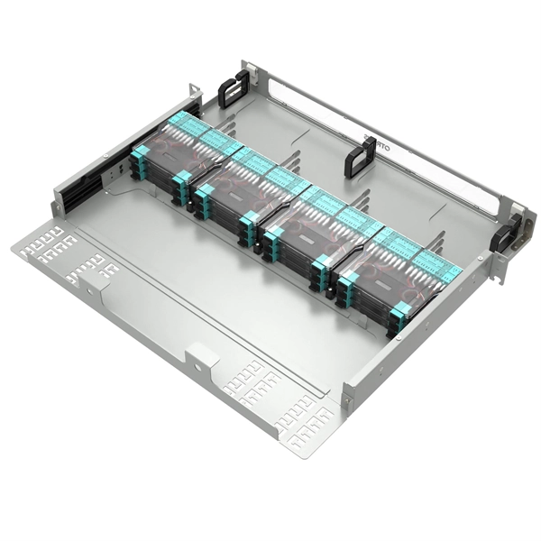
How long should the optical fiber be left in the optical distribution box
Since the front panel of the optical fiber distribution box can be pulled out, the length of the optical cable trunk in the distribution box should be long enough. Firstly, capacity and compatibility are essential factors to evaluate. (FOA) was founded in 1995 to help develop the workforce to build the fiber optic networks to support a rapid expansion in communications and the Internet. The charter of the FOA was to promote professionalism in fiber optics through education, certification, and. To address this problem, the fiber termination box (FTB) was created to protect the fragile fiber terminals and provide a simple and clear way to manage the incoming and outgoing cables.
[PDF Version]
-
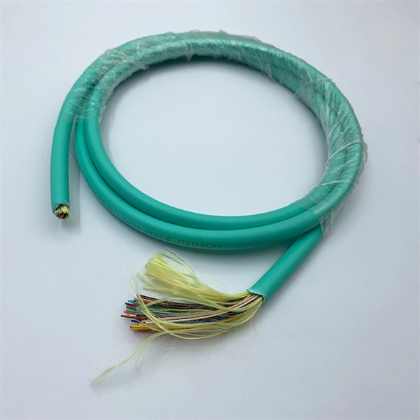
Color sorting of 192-core optical fiber cable
This guide explains the latest EIA/TIA-598-D fiber color-coding standard used to identify fiber types, inner fiber sequences, and connector polish styles. With clear tables and updated details, it serves as a comprehensive reference for technicians handling modern fiber optic. Understanding fiber‑optic color codes is essential for any technician tasked with installing, maintaining, or troubleshooting modern fiber networks. By adopting the TIA/EIA‑598C standard, you gain a universal “language” of colors that speeds identification, reduces miswiring, and enhances safety. This Applications Note addresses Corning Optical Communications' identification scheme for optical fiber cables. This identification scheme follows the TIA/EIA-598, “Optical Fiber Cable Color Coding. Hexatronic offers cables with color code systems according to all interna ional and national standards and for all types of fiber opti such as a tube, ribbon, yarn wrapped bundle or other types of bundle.
[PDF Version]
-
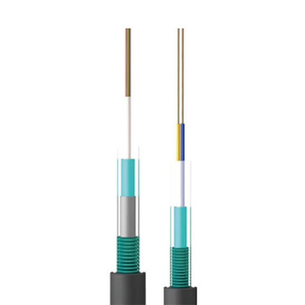
The Black Box of Optical Fiber Cable Manufacturing
This educational documentary covers every step of production in a modern industrial facility. Topics covered in this video: Fiber Drawing: High-precision melting and pulling of glass fibers. Stranding: Bundling fibers for high-capacity data. Choose pre-terminated multi-strand fiber cables, patch cables/panels, Active Optical Cables (AOCs), & bulk fiber cable. Our fiber assemblies reduce the time and cost associated with on-site cable. tal applications. Black Box provides a wide selection of high-quality, guaranteed-for-life distribution tight buffer indoor and indoor/outdoor cable and loose-t with no minimums. Expected in-stock date for this item is between 7-9 days. We have more than 15 years of experience in the Fiber optic communication and FTTx network field, focus on production, R&D and sales of passive fiber optical products and FTTA/FTTH/FTTR solutions. Usually Core Coating Strengthening Cable Jacket fiber optic cables contain several fibers, a strong central strength m mechanical protection.
[PDF Version]
-
Reasons for messy optical fiber cables
Outdoor fiber cables are exposed to temperature changes, moisture, and rodent damage. These factors can weaken the cable jacket and affect performance over time. Though fiber optics is known for reliability, it is not invulnerable. Every fiber optic cable installer or a company that deals in optical installation needs to know the reasons behind. Fiber-optic cables are the backbone of modern connectivity—powering 5G networks, global internet backbones, and data center interconnections with near-light-speed data transmission. Even. A well-built fiber link rarely fails, but when it does the symptoms can be short, confusing, and expensive to chase. This guide lists the actual, field-proven problems technicians encounter most often and gives step-by-step troubleshooting actions you can copy into your maintenance routine. Despite their durability, fiber optic cables can suffer from physical stress. Get to know straight from the fiber optic installers and identify the common causes of fiber optic cable damage to have a solid network infrastructure.
[PDF Version]
-
The maximum distance of long-distance optical fiber cables
Max Length: Up to 100 kilometers (62 miles) or more without needing signal boosters or amplifiers. Usage: Single-mode fiber is ideal for long-distance communication, such as connecting cities or telecommunications over vast regions. The maximum transmission distance varies significantly between fiber types, with single mode fiber offering substantially greater range than multi mode fiber alternatives. Single mode is typically used for. The more power coupled into the fiber, the longer the transmission distance. Single-mode. The maximum reach of a fiber optic cable is not a property of the cable alone — it is the result of a balance between the link attenuation and sensitivity of active equipment A single OS2 cable can carry 1 Gbps over 100 km with suitable modules, or only 10 Gbps over 10 km with standard modules.
[PDF Version]
-
How to separate the fiber cores of OPGW24-core optical cable
Removing the aluminum strands and outer layers of the OPGW cable exposes the fiber optic cores 7, which is essential for proper termination. Use a file to smooth any sharp edges after removing the aluminum strands 8. Carefully separate the metal loose tubes without damaging. Proper termination of OPGW cables involves precise steps like careful handling 3, removing outer layers, cleaning fibers, and securing with clamps. In the construction of electric power dedicated communication network, the number of optical fibers used is usually 12 to 24 cores. With the continuous expansion of system capacity according to new business requirements, the number of cores is gradually increasing, and individual line sections have. out this step, cut a small piece of pipe, about 2 feet, from the free end of the cable and practice cuttin of the cable. While holding the cable, pull the optical units completely out of the pipe by pullin toward the tower. What is Fiber Optic Splicing and Why is it Needed? – #1. First, a heat-shrink tube is placed over the OPGW cable.
[PDF Version]
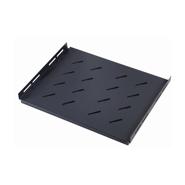
Telecom Racks & Cabinets
19-inch racks, wall-mount cabinets, open frames with high load capacity and seismic rating.
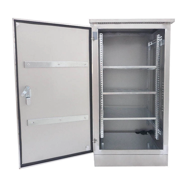
Outdoor Climate Cabinets
IP55/IP66 outdoor enclosures with integrated cooling/heating, -40°C to +55°C operation.
Smart PDUs & Power Distribution
Intelligent PDUs with remote monitoring, per-outlet switching, and environmental sensors.
Shelters & Network Cabinets
Prefabricated telecom shelters, emergency comms shelters, and network cabinets with cable management.