-
How to make an optical fiber splice
Learn how to splice fiber optic cable using fusion splicing with this complete step-by-step guide. Includes tools, best practices, loss standards (ITU-T G. 652), cost analysis, and FAQs for network engineers and installers. Ensure Your Splicing Tools are Clean – #2. Use and Maintain Your. Think of a fiber optic cable splice as the seamless stitching that keeps data flowing through the delicate threads of a network—like a master tailor joining fabric with precision.
[PDF Version]
-
Acceptance Requirements for Optical Fiber Cable Splicing
IPC-A-640, officially titled “Acceptance Requirements for Optical Fiber, Optical Cable, and Hybrid Wiring Harness Assemblies,” provides acceptance criteria for cable and wire harness assemblies that incorporate optical fiber technology. The Contractor tasked to perform testing or splicing on any fiber optic cable will follow these testing standards to fulfill their contractual obligations. This testing. METR IBER MEDIA NET WORK Fiber Optic Cable Splicing, Testing and Acceptance Criteria for Contractors Version 1. Typical applications of these methods include aerial, buried, and underground splices. (2) American National Standard Institute/National Fire Protection Association (ANSI/NFPA) 70, 1993. d suppliers of electrical construction services. Unlike copper wire harnesses where a slightly imperfect crimp might still conduct electricity, a contaminated fiber end face or improper splice can completely block light transmission. The contractor submits test results. And then someone — usually someone who hasn't done this before — tries to figure out whether.
[PDF Version]
-
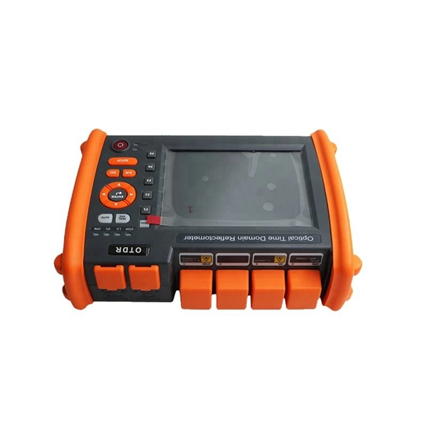
How to determine if an optical fiber is connected to a splitter
Testing a splitter or other passive fiber optic devices like switches is little different from testing a patchcord or cable plant using the two industry standard tests, OFSTP-14 for double-ended loss (connectors on both ends) or FOTP-171 for single-ended testing. They have been used since the 1980s to create networks and provide the technology for today's passive optical networks used in fiber to the home. When you pick a splitter, look at the split ratio. Less insertion loss means your signal is better. Test splitters and couplers often to keep them working well. What Is an Optical Coupler? An. A fiber optic splitter is a passive optical component that divides a single incoming optical signal into two or more outgoing signals, or combines multiple incoming signals into one. Rarely, there can be two inputs to provide potential redundancy of route.
[PDF Version]
-
How much does 24-core optical fiber cable cost per meter
In practical terms, the current market range for a standard single-mode 24 core fiber optic cable typically falls between $1. For instance, a 24 core fibre optic cable price in Europe may differ from that in Southeast Asia due to transportation costs and regulatory requirements. These cables are available in both single-mode and multimode variants, each engineered for specific network requirements ranging from long-haul. Single-mode fiber (OS2): This is the industry workhorse. In 2025, the base glass price has stabilized. The price swing usually depends on the fiber count (e., 12-core vs 96-core) and brand. Commercial building installations with 100-200 network drops generally range from $15,000 to $30,000. Single-mode fibers (SMF) are typically used for long-distance. Knowing how much fiber optic cable costs, which factors can impact cost, and key cost considerations can help you avoid unnecessary expense and get the most out of your budget.
[PDF Version]
-
Remaining fiber cores in optical cable
First, clearly understand the number of wiring points and calculate the number of switches. Whether the connections between switches are stacked is also one of the considerations. Stacking: If the core switch i.
[PDF Version]
-
No change in optical fiber sensor light intensity
This function is effective when the intensity value does not change (saturation) from the maximum value of the display-possible range in using the fiber unit at close range. * To disable this function, press. Among the reasons why optical fibers are such an attractive are their low loss, high bandwidth, immunity to electromagnetic interference (EMI), small size, light weight, safety, relatively low cost, low maintenance, etc. At the heart of this technology is the optical fiber itself -- a hair-thin. A fiber optic sensor is a measurement device that uses light traveling through a glass or plastic filament to determine a physical quantity such as temperature, pressure, or strain. These sensors replace traditional electronic sensors by using light waves instead of electrical signals. The optical. Press and hold the and buttons simultaneously for three seconds. Use the to select "rSt", then press the button.
[PDF Version]
-
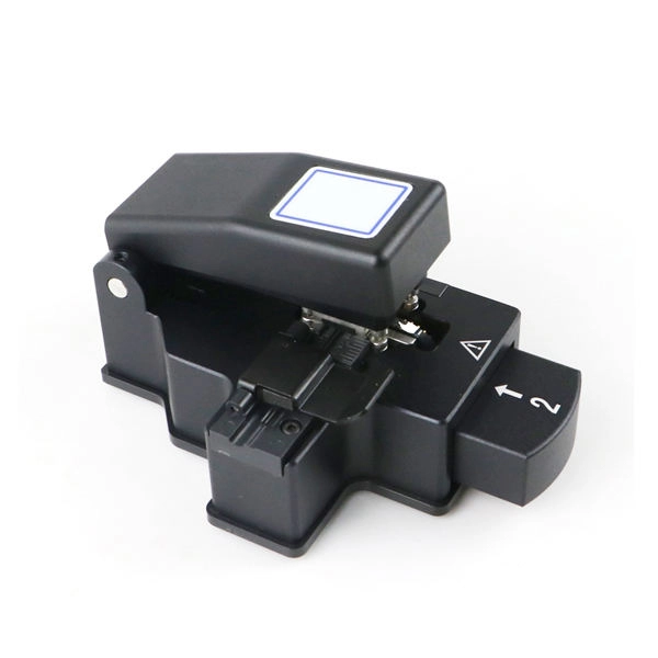
What dB value is considered acceptable for optical fiber splicing
Acceptable splice loss in optical fiber is typically considered to be less than 0. What is the typical acceptable splice loss for single-mode fiber using fusion splicing? What is the acceptable splice loss for multimode fiber using mechanical splicing? How does fiber alignment affect splice loss? Why is cleaning the fiber important before splicing? What role does the cleaver play. Acceptable dB loss for fiber depends on the component you're measuring: a single mated connector pair should lose no more than 0. 5 dB per kilometer depending on the type and wavelength. The total. However, acceptable values depend on: * Project specifications * Link budget calculation * Network type (FTTH vs backbone) * Customer SLA requirements 🛠 Fusion vs Mechanical Splicing * **Fusion splicing** typically gives lower loss (0. * **Mechanical splicing** usually results in. The splice loss is measured in decibels (dB) and is influenced by various factors such as the quality of the splice, the alignment of the fiber cores, and the type of splicing technique used. 5 dB, while for multimode. For each connector, we usually figure 0. However, various factors, such as fibre cleanliness, core.
[PDF Version]
-
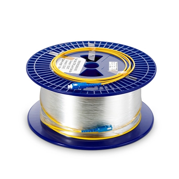
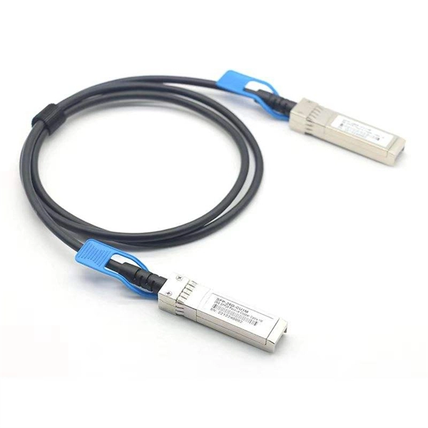
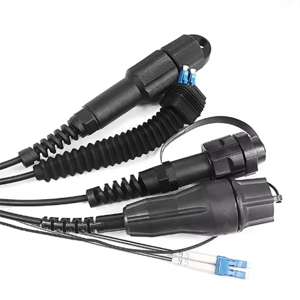
Is flexible optical fiber the same as a pigtail
When you build or upgrade a fiber network, the same four words pop up everywhere— fiber optic (bare fiber), pigtail, patch cord, optical cable. They're related, but they are not interchangeable. Mixing them up drives costs higher, increases loss, and slows your rollout. The good news? Once you nail. Executive Summary: A fiber optic pigtail is one of the most commonly specified yet least understood components in structured cabling. Get the wrong connector type, the wrong polish, or skip proper fusion splicing technique—and you're looking at elevated signal loss, increased back reflection, and a. Dual Connectors: Both ends are fitted with standardized connectors (e., LC, SC, ST), which may be identical (e. It is usually suitable for field termination using a mechanical or fusion splicer. But what exactly is a pigtail and why do you use it? In this article, we explain why they are important and which pigtail connector you should choose, with a focus on SC and LC pigtails. What is a pigtail? A pigtail is used to.
[PDF Version]
-

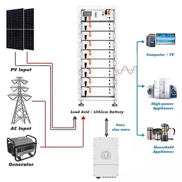
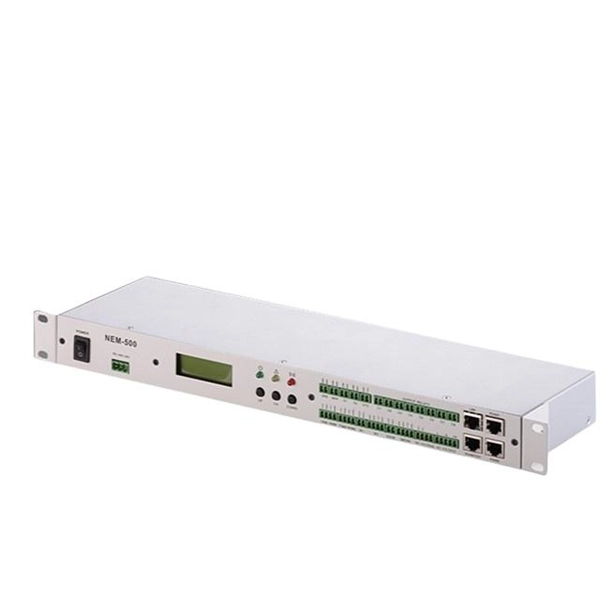
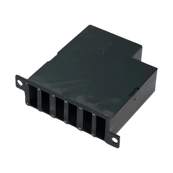
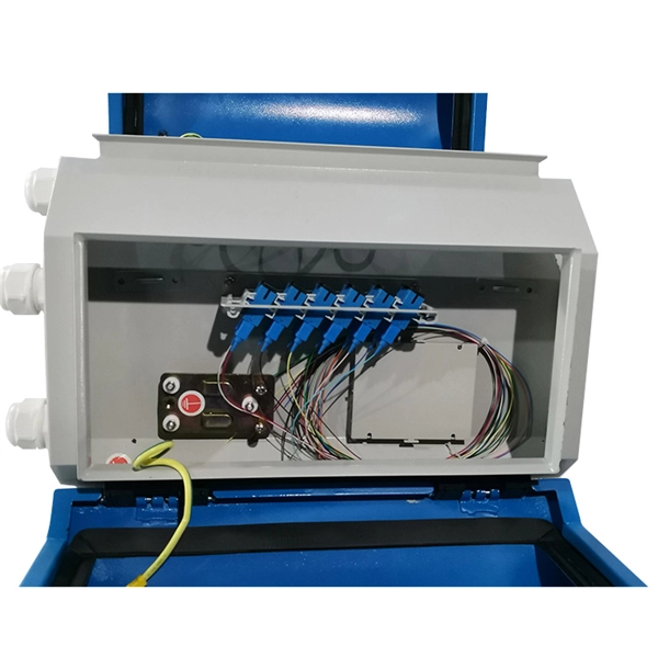
Will the optical fiber distribution box have a BBU
It sits in an enclosure with the Battery Backup Unit (BBU) and associated wiring. It has an optical port connecting to the external Customer Splice Point, an Ethernet port connecting to the communications provider's (CP) router, and a telephony port connecting to the voice. units on towers, buildings, or light posts. The RRU is normally located at the top of a tower, roof, or similar bu lding object and very close to the antenna. On the other end, the. RRU and BBU are crucial components in base station construction, enabling a distributed architecture that improves efficiency and reliability. In a distributed base station. Fiber Optic Distribution Box (FDB) / Fiber access terminal box (FAT) / optical termination box (OTB) / Fiber termination box (FTB) / Optical Distribution box (ODB) are a compact fiber management box used for FTTH application. For more. The enclosure is attached to the wall with 2 screws, instead of the 4 on the previous ONT A template is provided with the unit to ensure correct screw location The enclosure will fit over a double back box to allow the connectorised cable to be inserted through the back of the unit.
[PDF Version]
-
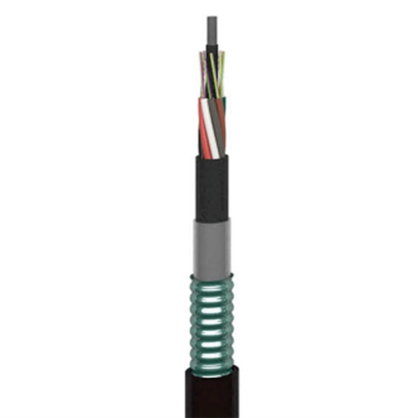
How many cores of optical fiber cable does Indonesia use
The deployed fiber-optic cable is based on Nexans' 24-core unrepeatered (URC-1) design. Near the shore, at water-depths below 20 meters, it will feature a double-armored (DA) construction for extra protection against damage from shipping and fishing activities. Telecommunication Statistics Indonesia presents data on the development of the telecommunications sector in Indonesia, which includes internet penetration rates, ownership of information and communication technology (ICT) facilities, usage patterns, as well as data on telecommunications networks. Indonesia - how many cores do I need for fiber optic cable internet connection, 1500 meters / 5000 feet How many cores do I need? I would run the cable myself above ground out of reach, using existing poles. This technician is trying to scam me with the cable (normal here). I am guessing I need. Indonesia Fiber Optics Market: Import Trend Analysis In the Indonesia fiber optics market, the import trend showed a growth rate of 0. The Palapa Ring project is also summarized, which aims to connect over 33 provinces and 460 districts across the. NEC Corp. For depths between 20 and 200 meters.
[PDF Version]
-
Does the polyethylene sheath of optical fiber cable contain formaldehyde
Generally speaking, the outer jacket of fiber optic cables is made of low smoke and halogen free materials (LSZH), cross-linked polyethylene (XLPE), and so on. Its primary functions include: While the optical fiber itself remains largely unchanged, the sheath material determines how the cable behaves in fire scenarios, outdoor environments, and long-term service conditions. The LSZH sheathed fiber optic cable can. Based on the density of the PE fiber cable outer sheath, there are also MDPE (middle density) and HDPE (high density). One of the primary advantages of PVC is its notable flexibility, which facilitates easy handling and installation, making it suitable for a broad range of. PE (Polyethylene) is a thermoplastic synthesized from the polymerization of ethylene (C2H4) under suitable pressure and temperature, widely used in the wire and cable industry. Disadvantages: Higher cost than PVC, generates a lot of black smoke when burning.
[PDF Version]
-
Optical cables are all based on the principle of optical fiber transmission
Fiber optic cables have revolutionized telecommunications, data transmission, and network infrastructure by offering a faster, more reliable means of communication. The core principles behind fiber optic transmission rely on optical technology, enabling the transfer of information. In this article, we will learn about Optical Fiber Light Transmission, Optical fiber light transmission is a technology that enables the transmission of data and information through thin strands of glass or plastic fibers using light signals. To. An optical fiber can be understood as a dielectric waveguide, which operates at optical frequencies. The device or a tube, if bent or if terminated to radiate energy, is called a waveguide, in general. fiber optics, the science of transmitting data, voice, and images by the passage of light through thin, transparent fibers.
[PDF Version]
-
Cable and Optical Fiber Survey Report
The report on the fiber optic cable market provides a holistic analysis, market size and forecast, trends, growth drivers, and challenges, as well as vendor analysis covering around 25 vendors. Fiber optic cables are needed for backhaul and fronthaul connectivity because they provide the required bandwidth for 5G base stations and small cell networks. Public cable companies lost 265,000 Internet customers in Q3 2024. 0 will significantly stem this trend. Where Are We Going? to telecom in the past five years (the majority to fiber). Disbursement occurs over multiple years. 19 billion by 2033, expanding at a CAGR of 10. Cable operators plan to carry out a growing number of network upgrades and new builds over the next 5 years, including FTTP-oriented, DAA-oriented, PON-oriented, DOCSIS-oriented, and. The UTC Fiber subcommittee serves as a platform for utility industry professionals and executives to address present and future challenges related to fiber optic networks. I need the full data tables, segment breakdown, and.
[PDF Version]
-
What are the methods for knotting optical fiber cables
The two primary industry-accepted methods for fiber optic cable splicing are fusion splicing and mechanical splicing. The choice between them depends on performance requirements, budget constraints, and the specific application environment. Discover the exact steps, adhere to stringent safety. Cable knots are a type of knot used to join two cables or ropes together, or to attach a cable to a post, rail, or other fixed point. They are designed to withstand heavy loads and stresses, making them ideal for applications where safety and reliability are paramount. What Is Fiber Optic Internet? Before diving into installation, it's important to understand what fiber optic internet is.
[PDF Version]
-
The Black Box of Optical Fiber Cable Manufacturing
This educational documentary covers every step of production in a modern industrial facility. Topics covered in this video: Fiber Drawing: High-precision melting and pulling of glass fibers. Stranding: Bundling fibers for high-capacity data. Choose pre-terminated multi-strand fiber cables, patch cables/panels, Active Optical Cables (AOCs), & bulk fiber cable. Our fiber assemblies reduce the time and cost associated with on-site cable. tal applications. Black Box provides a wide selection of high-quality, guaranteed-for-life distribution tight buffer indoor and indoor/outdoor cable and loose-t with no minimums. Expected in-stock date for this item is between 7-9 days. We have more than 15 years of experience in the Fiber optic communication and FTTx network field, focus on production, R&D and sales of passive fiber optical products and FTTA/FTTH/FTTR solutions. Usually Core Coating Strengthening Cable Jacket fiber optic cables contain several fibers, a strong central strength m mechanical protection.
[PDF Version]
Telecom Racks & Cabinets
19-inch racks, wall-mount cabinets, open frames with high load capacity and seismic rating.
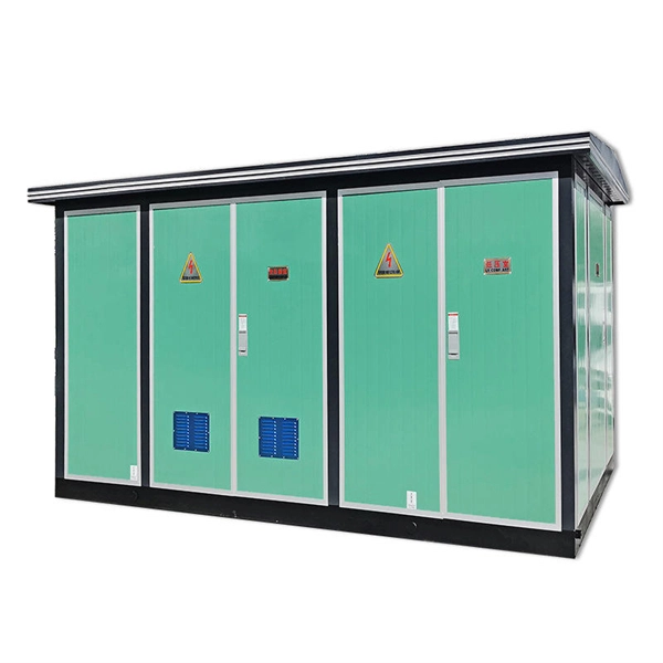
Outdoor Climate Cabinets
IP55/IP66 outdoor enclosures with integrated cooling/heating, -40°C to +55°C operation.
Smart PDUs & Power Distribution
Intelligent PDUs with remote monitoring, per-outlet switching, and environmental sensors.
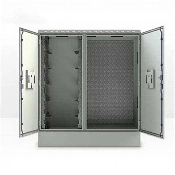
Shelters & Network Cabinets
Prefabricated telecom shelters, emergency comms shelters, and network cabinets with cable management.