-
Crystalline Silicon for Optical Fiber Communication
Silicon-core fibres have unlocked new regimes of mid-infrared transmission, on-fibre Raman amplification and nonlinear wavelength conversion, finding relevance in gas sensing, biomedical diagnostics, high-power laser delivery and all-optical signal processing. Silicon-core optical fibres represent a convergence of semiconductor photonics and conventional fibre technology, embedding a crystalline silicon or silicon–germanium alloy core within a glass cladding. This architecture combines the high refractive index contrast and pronounced nonlinear response. Polycrystalline silicon core optical fibers have been fabricated by modified thermal annealing of amorphous silicon chemically deposited at high pressure. The resulting fibers have small-diameter cores, a geometry advantageous for optical guidance. Moreover, the combination of chemical deposition. Novel core fibers have a wide range of applications in optics, as sources, detectors and nonlinear response media. Optoelectronic, and even electronic device applications are now possible, due to the introduction of methods for drawing fibres with a semiconductor core. Here we explore the underlying.
[PDF Version]
-
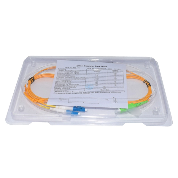
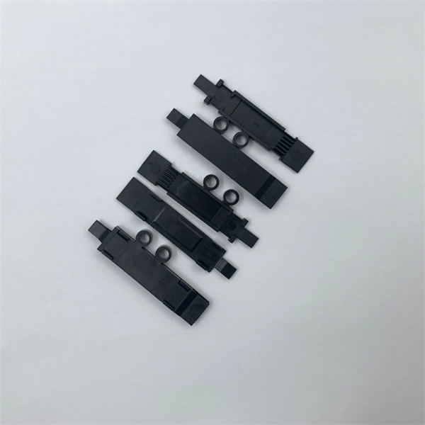
Sudan optical splitter miniature plug-in low loss vs wireless
This paper aims to study the design, simulation, and optimization of low-loss Y-branch passive optical splitters up to 64 output ports for telecommunication applications. For a waveguide channel profile, the standard material silica-on-silicon is used. Testing a splitter or other passive fiber optic devices like switches is little different from testing a patchcord or cable plant using the two industry standard tests, OFSTP-14 for double-ended loss (connectors on both ends) or FOTP-171 for single-ended testing. Splitters are essential when you want one fiber line from a central office (like an ISP's headend or data center) to serve multiple homes or businesses. These splitters feature a rugged miniature housing to fit into compact spaces in equipment and systems. It can distribute the optical energy transmitted through a single fiber to two or more fibers in a predetermined ratio or combine the optical energy from multiple fibers into one fiber.
[PDF Version]
-
Reasons for the low return loss of optical splitters
See below for how OTDRs measure reflectance and return loss. Mechanical splices have index matching gel to prevent reflections. In fiber optic networks, particularly in FTTx (Fiber to the x) and PON (Passive Optical Networks) deployments, splitters play a central role in distributing the optical signal from a single source to multiple destinations. When high-speed signals enter or exit a part of an optical fiber, such as an optical fiber connector, discontinuity and impedance mismatch may cause reflection, which is the return loss of an optical fiber.
[PDF Version]
-
Long-distance optical transceivers with low loss 2026 model CE certified
Explore the critical role of telecom grade C-band transceivers in long-distance optical transmission, with specs, deployment insights, and expert guidance. Compared with 850nm or 1310nm SFP modules, 1550nm SFPs are designed for scenarios where signal attenuation, link budget. In the modern network, transceivers are categorized primarily by their reach (distance) and media type (Multimode vs. Miscalculating these distances leads to bit errors and link failures that can cripple a mission-critical environment. Hyperscale Data Centers: High-density spine-leaf. In the rapidly evolving landscape of hyperscale data centers, 5G Open-RAN architectures, and enterprise campus backbones, the optical transceiver has graduated from a commodity component to a critical strategic asset. From short-reach SR4 (hundreds of meters) to intermediate-reach LR4 (up to 10 kilometers), and further to. The Innoptical's IN-C2DCO-200G-LH coherent module, utilizes a trio of indium phosphide (InP) based PICs, covering the laser, modulation, and receiver functions. Through integration, we have enabled almost complete on-wafer test of our PICs. We have a FAE team to provide tailor-made network.
[PDF Version]
-
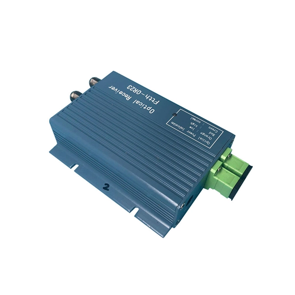
Local Area Network Optical Transmitter Low Temperature Resistance Global Shipping
Long-Haul Capability: Integrated with 8-channel cooled EML lasers and photodetectors, GIGALIGHT's 8-Channel LAN-WDM optical transceivers offer LR8 options for 10km/20km long-haul transmission, ideal for data centers, telecommunication networks, and 5G mid-haul applications. GAOTek optical transmitter develops into triple-play step by step. This is realized by fiber access with EPON, GPON networks. In 1550 nm system, it has been a huge topic for the network operators how to inter-cut local. Explore how AI clusters are reshaping network architecture, from XPU-centric design to multi-plane scalability, and learn how 800G modules enable high-performance, low-latency interconnects for modern AI data centers. This innovative masterpiece, integrating eight channels into one, is rewriting the future of optical communication at an astonishing pace. These transmitters vary significantly in design, performance, and application based on the light source and fiber type. From precision instruments to field and job-site essentials, we're your trusted source for quality tools. Ohmite 's new HVS series are aluminum housed resistors available in 25W or 50W.
[PDF Version]
-
Electromagnetic waves communicate via optical fibers
Fiber optic communication relies on transmitting information as pulses of light through thin strands of glass or plastic called optical fibers. Instead of using electrical signals (like in traditional copper wires), it uses electromagnetic radiation in the form of light. This technology has revolutionized data transmission, enabling high-speed, long-distance communication for. Light is part of the "electromagnetic spectrum" that also includes x-rays, ultraviolet radiation, microwaves, radio, TV, cell phones, and all the other wireless signals. We refer to the range of wavelengths of electromagnetic. When light travels through an optical fiber, only reflections at a certain angle are reflected repeatedly due to the relationship between the difference in refractive index (between the core and cladding of the optical fiber) and the thickness of the core.
[PDF Version]
-
Commonly used polarization-maintaining optical fibers
Different types of polarization-maintaning fibers are designed depending on the geometry of the stress elements: “PANDA“ fibers, “Bow-Tie“ fibers or “Oval-Inner Clad“ fibers. In fiber optics, polarization-maintaining optical fiber (PMF or PM fiber) is a single-mode optical fiber in which linearly polarized light, if properly launched into the fiber, maintains a linear polarization during propagation, exiting the fiber in a specific linear polarization state; there is. 📦 For purchasing, use the RP Photonics Buyer's Guide for polarization-maintaining fibers. It provides an expert-curated supplier directory, buyer-focused technical background information, and structured selection criteria to support professional procurement decisions. The light is then guided in two perpendicular principle states of polarization with different propagation constants – the fast and the slow axis.
[PDF Version]
-
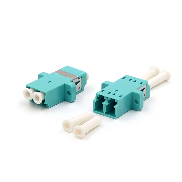
How much loss is there in an optical cable connector
A typical fiber connector has an insertion loss of around 0. How can insertion loss be measured? A common method is optical time-domain reflectometry, which can separately measure the loss of multiple. Insertion loss, also known as attenuation, is the loss of optical power that occurs when light passes through a fiber optic connector. It is caused by factors such as misalignment, air gaps, and imperfections in the connector components. Unfortunately, it is not a simple answer and depends on several factors. This article explores various connector types—such as SC, LC, FC, ST, APC, and UPC—and analyzes how their design and polishing affect IL and RL performance. Insertion Loss (IL): Measures the. Fiber loss, also called fiber optic attenuation or attenuation loss, refers to the loss of signal between input and output.
[PDF Version]
-
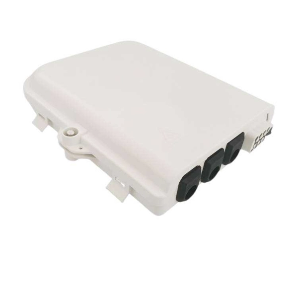
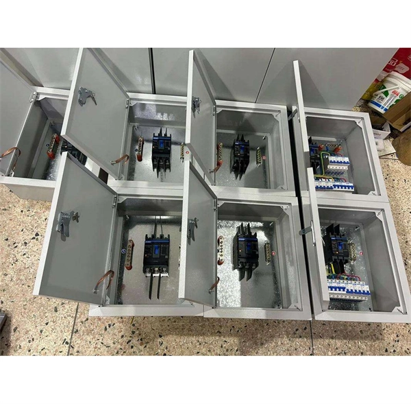
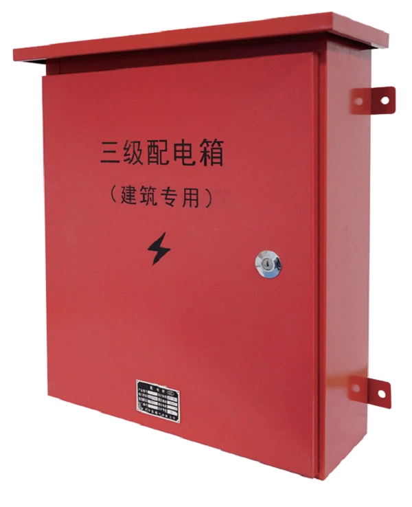
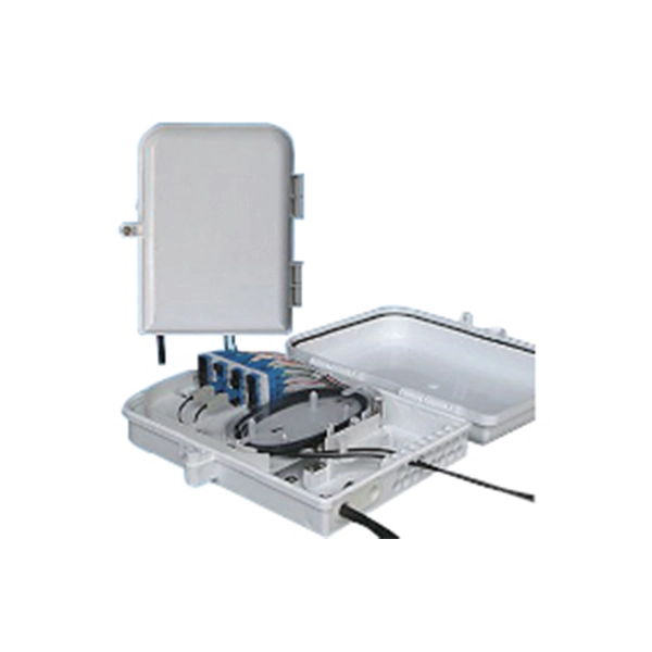
Low Noise Warranty for Optical Cable Terminal Boxes Used in Mining
Explore reliable optical fiber splice closures for network deployment. Our closures prioritize reliability, installability, and flexibilityOf all the Fiber Optic Cable Companies in the world, no one has a better reputation for reliability than OCC. Much of that is due to our commitment to the most rigorous testing and assurances. Here's. Seller's only warranties to Buyer are that on the date of shipment, all goods manufactured by Seller shall be free from defects in material and workmanship under normal use and service. any goods manufactured by a third party. Trunk and Feeder Network Solutions: These closures are designed for robust performance in the backbone of. The term Low Noise Cable is a term that Systems Wire and Cable is very familiar with. Clearfield ® CraftSmart ® Fiber Protection Vaults (FPVs) meet and exceed industry standards for strength, reliability and environmental concerns. This product is 8-Core Wall Mount Fiber Optic Box with electrostatic spraying, 2 inlet ports, durable CRS steel, 9-year warranty for Data Center FTTX.
[PDF Version]
-
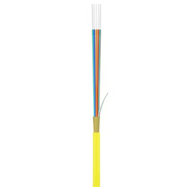
Can outdoor black optical fibers be made into multimode
All three formats can be built with either single mode or multimode fiber (single mode being far more common for several reasons — learn more) and in a variety of strand counts. These cables are specifically designed to ensure reliable connections in outdoor applications. Multi-mode links can be used for data rates up to 800 Gbit/s. Multi-mode fiber has a fairly large core diameter that enables multiple light modes to be. Single-mode (SMF) and multi-mode fiber (MMF) use different core sizes, sources and wavelengths. These differences determine which transceivers work with which fiber and how far signals can travel. Understanding the compatibility constraints prevents costly downtime and troubleshooting. Single-mode. Product Description This is a black 1000 foot spool of indoor/outdoor rated fiber optic distribution cable intended for large installations of short range runs at LAN Speeds. 5 microns, compared to the ~9-micron core in single-mode fiber.
[PDF Version]
-
Can optical fibers and optical modules communicate
Q: Can optical modules be interconnected with fiber optic transceivers? The answer is yes. Operating at the physical layer of the OSI model, optical modules are core devices in optical. That is, metal medium communication represented by coaxial cables and network cables is gradually being replaced by optical fiber media. Composition of Optical Modules The optical module, known as Optical Transceiver in. This combination of this plus optical fiber (a high-performance transmission medium made of glass as thin as a human hair capable of trapping optical signals and transmitting them over long distances without significant attenuation) were game changers and set the stage for optical-based. Optical modules and fiber optic transceivers are both important devices in fiber optic communication systems, is there any difference between them? How to choose? This article will introduce the difference between the two and the precautions to be taken when connecting. Photonic systems are usually analyzed in terms of individual photons, although wave methods still.
[PDF Version]
-
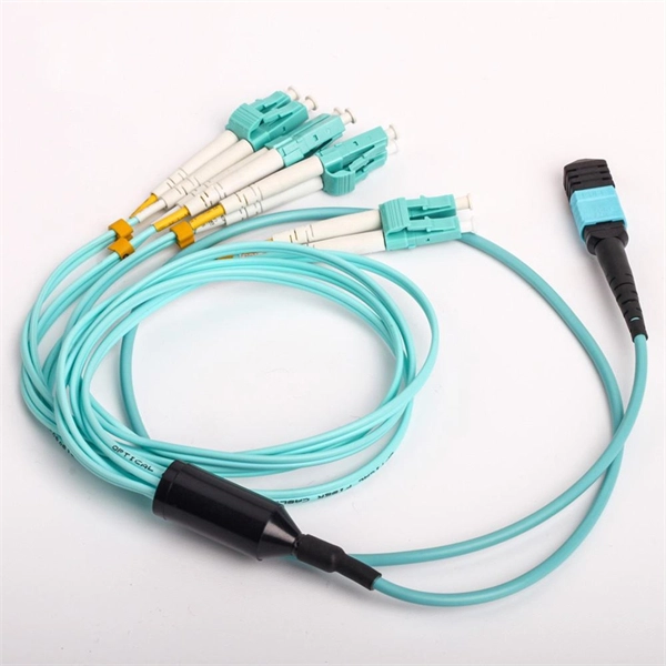
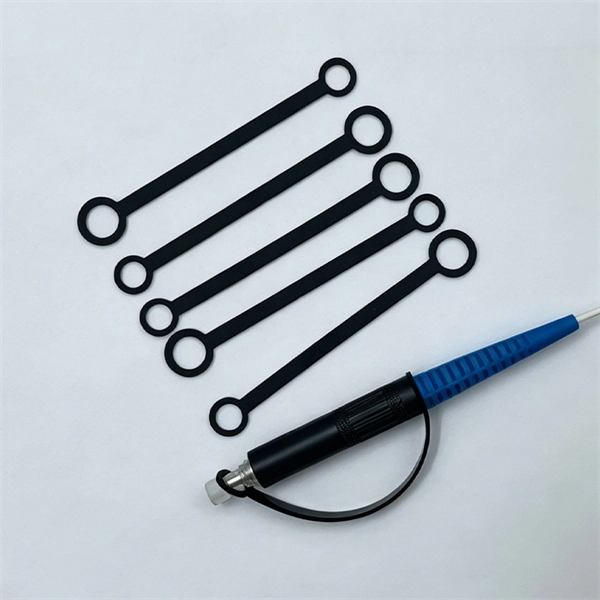
Can pigtails be used as optical fibers or cables
A pigtail is used to provide fiber optics with a connector. This creates a stable and reliable connection between network. Fiber pigtails are simple in appearance, yet essential in function. Get the wrong connector type, the wrong polish, or skip proper fusion splicing technique—and you're looking at elevated signal loss, increased back reflection, and a. The most urgent stage of the process is, in fact, separating fiber optic pigtail, also known as pigtail fiber or pigtail fiber optic cable. Characterized by having an optical fiber connector on one end and a bare fiber end on the other, they are primarily used to connect optical transceivers or other optical. A fiber optic pigtail is a type of fiber optic cable with only one end that has a factory-terminated connector and the other end exposed as bare fiber.
[PDF Version]
-
How to reduce optical loss in optical cables
Attenuation makes signals weaker in fiber optic cables. Check your optical transceiver's specs often. Scattering losses result from microscopic variations in the fiber's material density, compositional fluctuations, structural inhomogeneities, and manufacturing defects. Reducing these losses requires. Fiber optic cable, which is lighter, smaller, and more flexible than copper, can transmit signals with faster speed over longer distances. This technology supports the high-speed data demands of the modern world, from global internet backbones to local network infrastructure. As modern networks demand higher bandwidth and reliability, understanding optical fiber loss mechanisms and implementing strategies for automatic power reduction has become critical. Clean connectors before you use.
[PDF Version]
-
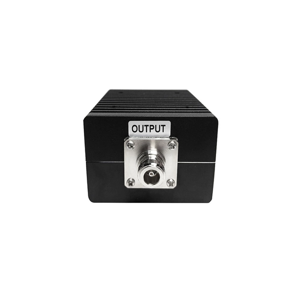
Packet loss in 10 Gigabit single-fiber optical module
For singlemode fiber, the loss is about 0. 5 dB per km for 1310 nm sources, 0. 1 dB per 600 (200m) feet for 1310. Key factors to consider in the design of 10 Gigabit Ethernet networks are: The network topology, including operating distances, splice losses and numbers of connectors (i. These modules offer low signal loss and minimal distortion, making them ideal for applications in metropolitan area networks and campus settings. Choosing the right fiber. The Cisco ® 10GBASE SFP+ modules (Figure 1) give you a wide variety of 10 Gigabit Ethernet connectivity options for data center, enterprise wiring closet, and service provider transport applications. When dealing with single mode fiber (SMF) in optical communication systems, understanding and managing the acceptable dB (decibel) loss is crucial for maintaining efficient and reliable signal transmission. They are compliant with SFF-8431, SFF-8432 and IEEE 802. 3ae 10GBASE-LR/LW, and 10G Fibre Channel 1200-SM-LL-L Digital diagnostics functions are available via a 2-wire serial interface. The transceiver is a “limiting module”, i. This article aims to explore this issue. 1 Attenuation Characteristics.
[PDF Version]
Telecom Racks & Cabinets
19-inch racks, wall-mount cabinets, open frames with high load capacity and seismic rating.
Outdoor Climate Cabinets
IP55/IP66 outdoor enclosures with integrated cooling/heating, -40°C to +55°C operation.
Smart PDUs & Power Distribution
Intelligent PDUs with remote monitoring, per-outlet switching, and environmental sensors.
Shelters & Network Cabinets
Prefabricated telecom shelters, emergency comms shelters, and network cabinets with cable management.