-
Custom Process for 850nm Hollow-Core Optical Fiber in Mining
This webinar explores the complete hollow-core fiber manufacturing chain and the Nextrom machinery that enables it. Beginning with preform manufacturing systems, it examines equipment designed to produce high-quality structures for hollow-core geometries. Compared to. M2 Optics offers a large portfolio of specialty optical fibers and components for high-speed aerospace, photonics, medical, automotive, and other advanced communications applications. But moving from prototypes to stable, repeatable production requires dedicated manufacturing systems. This. Hollow-core optical fibers (HCFs) have unique properties like low latency, negligible optical nonlinearity, wide low-loss spectrum, up to 2100 nm, the ability to carry high power, and potentially lower loss then solid-core single-mode fibers (SMFs). 6 dB/km and phase birefringence of 1.
[PDF Version]
-
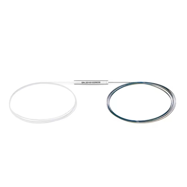
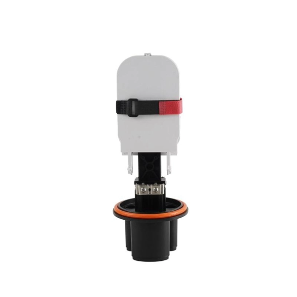
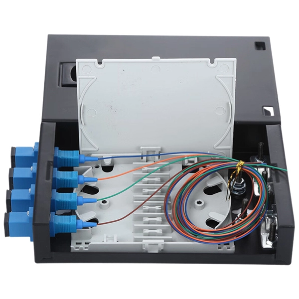
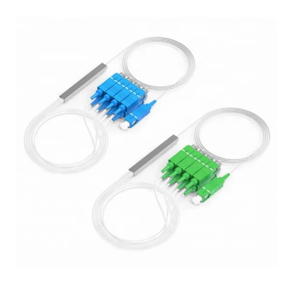
How many ports does the optical fiber splitter distributor have
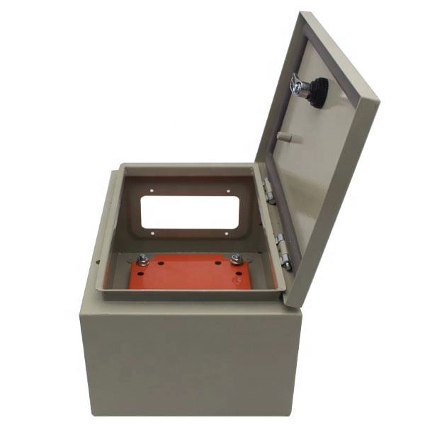
Featuring 24 fiber ports, comprising 3 inlet, 16 outlets, this fiber optic splitter box ensures seamless connectivity across your fiber optic infrastructure. Cost Efficiency: A single OLT port can serve 8–64 ONTs via a splitter, reducing the number of OLTs, fibers, and deployment labor needed. Passive Operation: Splitters have no active electronics, so they require no power, cooling, or maintenance—lowering operational costs (OPEX) for ISPs. Indoor/Outdoor Wall Mounted, Single Door Fiber Distribution box is ideal for end terminations of fiber optic runs in residential or commercial buildings. Integral gasket seal provides IP65 level of protection. Pre-installed with 24 SC/APC simplex couplers and two 1x8 terminated SC/APC splitters, it effortlessly supports single-mode fiber optic. A fiber broadband provider typically determines and overall split ratio for the network, such as 1x32 or 1x64, and uses combinations of splitters to meet that ratio with each PON port. 1x32 splits were common in North America for G-PON architectures.
[PDF Version]
-
72-core optical fiber cable fiber color military markings
This guide explains the latest EIA/TIA-598-D fiber color-coding standard used to identify fiber types, inner fiber sequences, and connector polish styles. With clear tables and updated details, it serves as a comprehensive reference for technicians handling modern fiber optic. This Standard provides all necessary information for color coding optical fiber cables in a uniform manner. This Standard was formulated as TIA Standards Proposal number ANSI/TIA-PN-598-D (old PN SP-3-3555-RV3-A) under the cognizance of TIA TR-42. 12, Subcommittee on Optical Fibers and Cables. This. Understanding fiber‑optic color codes is essential for any technician tasked with installing, maintaining, or troubleshooting modern fiber networks. By adopting the TIA/EIA‑598C standard, you gain a universal “language” of colors that speeds identification, reduces miswiring, and enhances safety. This Applications Note addresses Corning Optical Communications' identification scheme for optical fiber cables.
[PDF Version]
-
Belarusian large-core optical fiber 1310nm
In this article, we explore the key characteristics, common applications, and important comparisons related to 1310nm optical modules. Used for medium-distance links in city networks. As part of the O-band (1260–1360 nm), it balances low dispersion, stable performance, and cost efficiency. This makes it widely adopted in data centers, enterprise backbones, and metro access. The product features an SFP+ package with an LC connector, a 1310nm DFB laser with a PIN photodetector, and supports up to 20km transmission on SMF with power dissipation under 1W. Or It is also suited for analog fiber transmission. Pricing (USD) Filter the results in the table by unit price based on your quantity. A. 10GBASE-LRM SFP+ Transceiver Module 1310nm 220m - FS. com FS United StatesFREE SHIPPING on Orders Over US$79 Contact Us United States / $ USD Sign in Sign up Search Recent Searches Change FREE SHIPPING on Orders Over US$79 United States HomeOptical Transceivers10/25/40/100G. SFP+, 1310nm, LR SMF 10km, 10G DDM, Corning 1LAN-SFPP-10GB-LR Compatible Integra manufactures the highest quality SFPP transceivers in the industry, designed to be 100% interoperable with all OEM platforms.
[PDF Version]
-
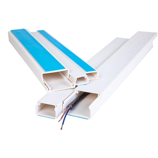
Does the optical fiber need to be wrapped with tubing
Spiral cut tubing (also known as spiral wrap) helps protect and bundle optical fibers for communication applications. PTFE and FEP spiral wrap are. The Installation After the process of designing fiber optic networks is completed, the next step is to install it. What do we mean by the “installation process?” Assuming the design is completed, we're looking at the process of physically installing and completing the network, turning the design. Fiber optic installation delivers unmatched network performance for modern businesses, providing greater bandwidth capacity and superior resistance to electromagnetic interference compared to traditional copper cables. Local company practices and/or vendor specifications may be in place concerning cable access and how it relates to a. When installing optical fiber cables, the requirements for wiring methods are located in Art. 770 references sections in Chapter 2 and Art. 22, which applies when. Fiber optic cable may be installed indoors or outdoors using several different installation processes.
[PDF Version]
-
Standard models of polarization-maintaining optical fiber
Different types of polarization-maintaning fibers are designed depending on the geometry of the stress elements: “PANDA“ fibers, “Bow-Tie“ fibers or “Oval-Inner Clad“ fibers. Image of the cross section of a polarization-maintaining optical fiber patch cord, taken with an illuminated microscopic viewer called a fiberscope. The two small, eye-like circles are the stress rods and the tiny circle between them is the core. Corning offers the broadest portfolio of PANDA PM fibers from wavelengths of 400-1550 nm and designs such as High NA and Flame Retardant coatings. It provides an expert-curated supplier directory, buyer-focused technical background information, and structured selection criteria to support professional procurement decisions. Its core principle is to utilize highly birefringent structures (such as stress zones or geometric asymmetry) to. In this article, the latest in FOC's series covering specialty fibers and their fabrication, we discuss polarization-maintaining (PM) fibers and the various approaches used to make them.
[PDF Version]
-
No change in optical fiber sensor light intensity
This function is effective when the intensity value does not change (saturation) from the maximum value of the display-possible range in using the fiber unit at close range. * To disable this function, press. Among the reasons why optical fibers are such an attractive are their low loss, high bandwidth, immunity to electromagnetic interference (EMI), small size, light weight, safety, relatively low cost, low maintenance, etc. At the heart of this technology is the optical fiber itself -- a hair-thin. A fiber optic sensor is a measurement device that uses light traveling through a glass or plastic filament to determine a physical quantity such as temperature, pressure, or strain. These sensors replace traditional electronic sensors by using light waves instead of electrical signals. The optical. Press and hold the and buttons simultaneously for three seconds. Use the to select "rSt", then press the button.
[PDF Version]
-
Source manufacturer of optical fiber cables for communication in Democratic Republic of Congo
Genew Technologies and Zhongshi Wosen, both Chinese companies, will help the Democratic Republic of Congo (DRC) build its fiber optic network. Our vision is to become the leading solution provider in Fiber Optic communication system by providing Leading Brands and 'state of the art' services. Its main product is the internet for professionals. Having therefore. The Democratic Republic of Congo (DRC) is poised for a significant boost in its digital infrastructure following the signing of a Memorandum of Understanding (MoU) between the Congolese Optical Fiber Company (SOCOF) and the Agency for Steering, Coordination and Monitoring of Collaboration. SOCOF is a one-person limited company in which the Congolese State is the sole shareholder. It is governed by the Uniform Act revised on January 30, 2014 relating to the law of Commercial Companies and Economic Interest Grouping and by all other laws and regulations in force in the DRC, not.
[PDF Version]
-
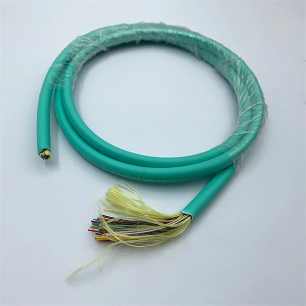
Complete List of Optical Fiber Cable Materials with Image
Each optical cable is constructed using a precise combination of optical fibers, strength members, buffer tubes, water-blocking elements, armoring, and protective jackets. Here is the extended technical table of all raw materials used in the fiber optic cable industry. ■ The Five Key Parts of a Fiber Optic Cable A fiber optic cable is composed of five core elements: Every hardware component has a specific function for proper signal transfer, construction resilience, and environmental defense. The choice of material is an engineering decision driven by the need to. Understanding the Core: The Heart of Fiber Optics The Cladding: A Critical Component for Containment Protective Coating: The First Defense Against the World Strength Members: Backbone of Fiber Optic Cables The Outer Jacket: A Shield Against the Elements Getting Flexible: Bend Insensitive Fibers A. A: PVC (polyvinyl chloride) is a widely used jacket material that provides good mechanical protection for fiber optic cables. PVC is fire-resistant but can release toxic fumes when burned.
[PDF Version]
-

How to select the number of optical cores in a fiber optic cable
The number of optical cores in an optical fiber is the total number of equipment interfaces multiplied by 2, plus 10% to 20% of the spare quantity, and if the communication mode of the equipment has serial communication and equipment multiplexing, you can reduce the number of cores. Fiber cores are the heart of fiber optic cables, transmitting light signals that carry data. Made from either high-quality glass or plastic, the core plays a critical role in determining the cable's performance.
[PDF Version]
-
Method for splicing and fusion of 6-core optical fiber cables
Learn how to splice fiber optic cable using fusion splicing with this complete step-by-step guide. Includes tools, best practices, loss standards (ITU-T G. 652), cost analysis, and FAQs for network engineers and installers. In this guide, you will find a chronological description of the fusion splicing process, the principal technical standards, and answers to the real-life questions network engineers and procurement teams may have. Therefore, we will also touch on cost factors, risk management, and best practices in. This is where fiber optic cable splicing—the process of creating a permanent, high-performance join between two fiber ends—becomes critical. When done right, splicing ensures minimal loss and long-lasting performance.
[PDF Version]
-
Standards for Optical Fiber Chromatography
Fiber‑optic standards resources from The Fiber School — detailed guides, industry standards and best practices for installation and certification. IEC Technical Committee 86 prepares International Standards for fibre optic systems, modules, devices and components intended for use with communications equipment. In particular, publications cover the area of tests, measurements and calibration ISO/IEC 17025 is a guide published by ISO. Science following a process that includes an open comment period. This Proposed Standard will be submitt Proposed Standard to other publications under development by OSAC. Standards have existed as long as. 'A document established by consensus and approved by a recognized body that provides for common and repeated use, rules, guidelines or characteristics for activities or their results, aimed at the achievement of the optimum degree of order in a given context'. Within the IEC there are various different committees. The TC86 is a sub-committee that is responsible for fiber optics similar to the TIA-568 standards in the US.
[PDF Version]
-
Is it normal to change electrodes in an optical fiber fusion splicer
Every 500 splices: perform electrode cleaning and automatic calibration. Clean the Splicer: Before installing the new electrode, clean any debris. This guide will help you understand the importance of electrode replacement, how to monitor electrode usage, and step-by-step instructions to ensure your fusion splicer operates at its best. Electrodes generate the arc discharge needed to fuse fibers together. What Are Fusion Splicer Electrodes? Fusion splicer electrodes are typically made of tungsten and are positioned opposite each other inside the. The fusion splicer electrode is the heart of any fiber optic fusion splicer, responsible for creating the precise electric arc that fuses glass fibers together. This guide delves into. Worn or dirty electrodes. Check the fusion counter in the maintenance menu.
[PDF Version]
-
What are the different methods of optical fiber fusion splicing
The two primary industry-accepted methods for fiber optic cable splicing are fusion splicing and mechanical splicing. The choice between them depends on performance requirements, budget constraints, and the specific application environment. Fusion splicing is the process of fusing or welding two fibers together usually by an electric arc. This technique ensures high-performance data transmission and is essential in extending cable runs, repairing broken links, or establishing new network paths in data. Fiber splicing means joining two optical fibers (permanently or temporarily) such that light guided in one fiber and reaching the joint (splice) can be transferred into the second fiber with low insertion loss. In this article, we will discuss the most commonly used optical.
[PDF Version]
-
Sequential splicing of optical fiber cores
This is accomplished with a machine called a fusion splicer that performs two basic functions: aligning of the fibers and melting them together, typically using an electric arc. ”This is where fiber optic cable splicing—the process of creating a permanent, high-performance join between two fiber ends—becomes critical. For network managers and technicians, a poor splice can lead to significant signal degradation, network downtime, and costly troubleshooting. Regardless of the type of fiber network you're deploying, be it for telecom, enterprise data centers, or smart city infrastructure, fusion splicing provides the benefits of. This application note provides basic understanding and process of mass fusion splicing of optical fiber ribbons. As explained in industry resources, this technique achieves insertion losses as low as 0. 01 dB and minimizes back reflection—critical for maintaining.
[PDF Version]
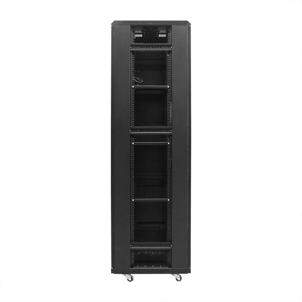
Telecom Racks & Cabinets
19-inch racks, wall-mount cabinets, open frames with high load capacity and seismic rating.
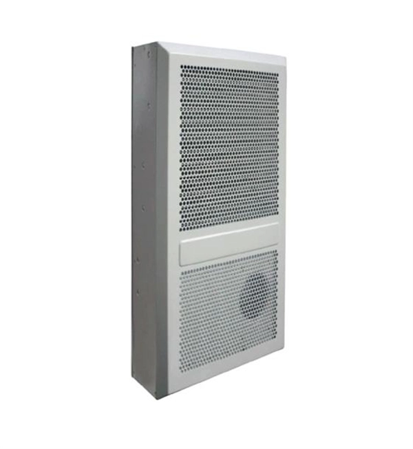
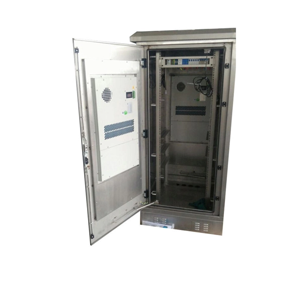
Outdoor Climate Cabinets
IP55/IP66 outdoor enclosures with integrated cooling/heating, -40°C to +55°C operation.
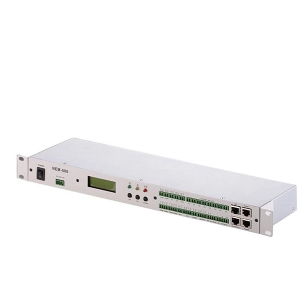
Smart PDUs & Power Distribution
Intelligent PDUs with remote monitoring, per-outlet switching, and environmental sensors.
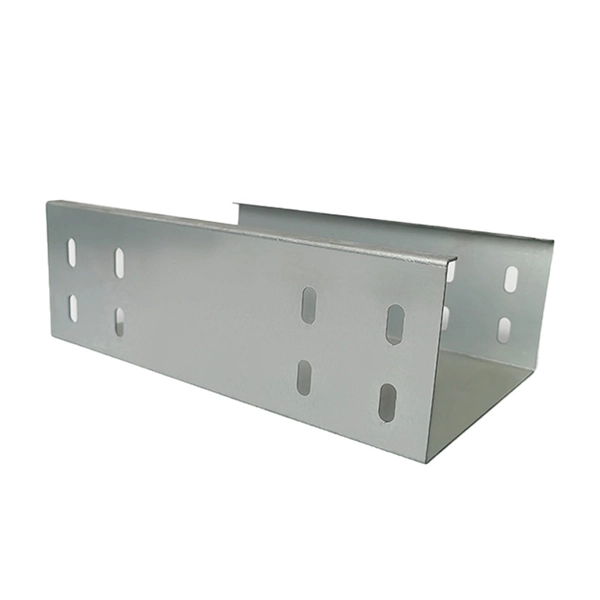
Shelters & Network Cabinets
Prefabricated telecom shelters, emergency comms shelters, and network cabinets with cable management.