-
Should the other end of the fiber optic patch cord be fused
Once you've selected your pigtail, the bare fiber end needs to be permanently joined to the incoming cable fiber. This is usually the shortest. Traditionally, fiber links are made where pairs of fibers are crossed between patch panels so fiber 1 at one patch panel will be connected to fiber 2 at the patch panel on the other end, fibers 3/4. Thus, when connecting patchcords, fiber 1 (or the odd numbered. Correct patch-cord installation is essential for maintaining low insertion loss, stable return loss, and long-term reliability in both indoor and outdoor fiber networks. The preparation process is far more than just stripping away layers of protective coating. According to data from NS Comm's Fiber Performance Lab (2024 Q4 Test Report), poor installation practices can cause up to 2. 5 dB additional signal loss.
[PDF Version]
-
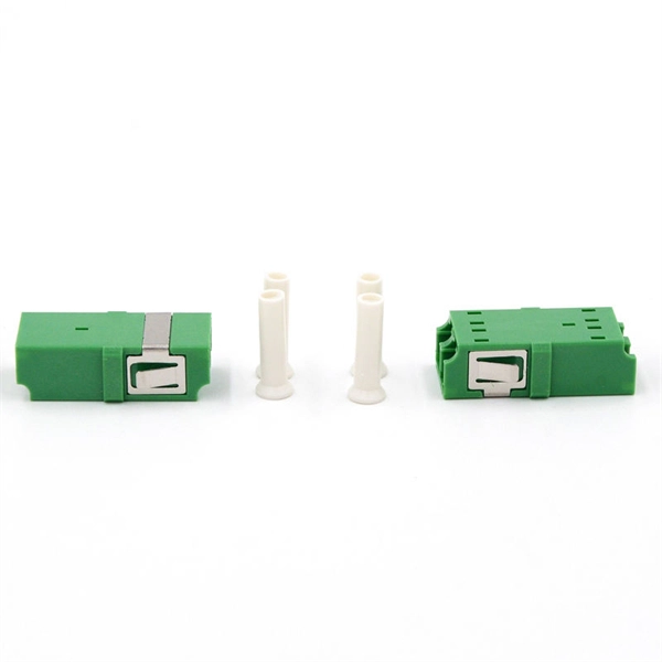
Are fiber optic patch cord boxes universally compatible with both ports Why
The patch cord must match the cable plant (e. Mismatching, especially using single-mode patch cords on multimode systems or vice-versa, will result in complete signal loss or severe degradation. Without them, even the best optical modules and switches cannot deliver performance. As data rates increase from 10G → 100G → 400G → 800G, patch cables must handle more bandwidth, more density, and stricter. A fiber optic patch cord (fiber jumper) is: Typical applications: A patch cord is the “bridge” that connects two fiber devices and lets them talk to each other. For indoor, short-distance applications (e. Whether back in the late 1990s or today, you will see 8P8C RJ45 type connectors at the end of Ethernet patch cords and keystone jacks mounted in walls running back to patch panels.
[PDF Version]
-
Which type of fiber optic patch cord has a larger quantity
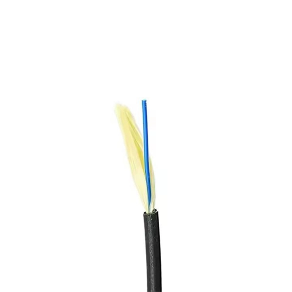
SC: larger, easy to handle, common in FTTH/CATV. Q3: What is the difference between simplex and duplex? Simplex = one fiber, one-way. Most Ethernet and PON links. Fiber patch cords, otherwise known as fiber optic jumpers or fiber optic patch cables, connect network equipment and transmit data using light signals over fiber optic strands. Understanding the various technical. They come in two types: Single-mode cables. Although these types share similar components (consisting of connectors and optical cables) and.
[PDF Version]
-
Fiber optic patch cord ferrule curing adhesive
The 353ND fiber optic epoxy glue is specifically designed for fixing optical fibers to ceramic ferrules in patch cord production. Fiber optic cables are the arteries of modern data transmission, silently carrying vast amounts of information at the speed of light. But what happens when these delicate glass strands. Master Bond offers an extensive line of epoxies and UV curing systems for use in fiber optics devices. Master Bond's adhesives contain no potentially objectionable contaminants and exhibit excellent resistance to. In high-speed fiber optic networks, ceramic ferrules play a pivotal role in aligning and protecting optical fibers. This two-component system consists of 353NDA and 353NDB, which must be used together in a fixed ratio of 10:1 (353NDA:353NDB). This application note provides.
[PDF Version]
-
What to do if the fiber optic patch cord connector is loose
Verifying the connector termination with a VFL tester and re-terminating solves the issue. Is a connection or patch point loose ? How many inline connections are in the run? Too many connections can cause too much signal loss. As. Proper installation and regular maintenance of fiber optic patch cords play a crucial role in achieving optimized network performance, preventing signal errors, and extending service life. The actual steps may vary depending on the cable and/or connectors. Fiber optic cables are typically damaged in one of two ways: A premade fiber optic cable suffers connector damage when too. Fiber optic patch cords are often treated as low-risk consumables, yet a large percentage of optical link failures originate at the patch cord level. Unlike backbone cables, patch cords are frequently connected, disconnected, bent, and handled by technicians, making them the most vulnerable. Ever notice your internet speed crawling or your industrial sensors lagging? Signal loss—also called attenuation—is often the culprit. Improper use of splicing equipment or environmental factors can introduce contaminants, leading to poor splice quality and.
[PDF Version]
-
Fiber optic patch cord storage requirements
The maximum storage temperature is specified for each cable in the datasheet and must be respected. Reels should be stored in areas with flat firm surfaces to prevent damage. GT-SCSCDM4A-xM fiber optic patch cords are ideal for short distance patching applications. These fiber optic cables have been built to exceed industry standards tested for insertion loss and reflectance on within UL certified OFNR (Riser) rated jacket with Kevlar yarn, and are factory terminated. Network decision-makers must evaluate several technical specifications before standardizing an MPO patch cable bill of materials: 1. Using Base-12 cables for Base-8 transceivers leaves 33% of. Whether you're cabling a new AI training cluster, upgrading a campus backbone, or just replacing aging patch cords in a colocation cabinet, this guide walks you through every decision point with actionable criteria. 1 What Is a Fiber Optic Patch Cable? 1. FO-VC2 JOINT USE - VERICAL MIDSPAN CLEARANCES 48. They are manufactured and tested in compliance with TIA 604 (FOCIS), IEC 61754 and YD/T industry standards.
[PDF Version]
-
Dual-core fiber optic patch cord manufacturing process
Explore the complete manufacturing and testing process of fiber optic patch cords, including polishing, assembly, and IL/RL testing. Discover how Gcabling ensures consistent quality for high-performance connectivity. This guide unveils the complete production workflow compliant with **IEC 61754** and **Telcordia GR-326-CORE** standards, featuring proprietary quality control methods. Its main purpose is to form a flexible, high-performance link between active equipment and optical networking devices such as patch. This guide offers a comprehensive overview of what it means to be a fiber patch cord manufacturer, their operations, capabilities, and quality assurance processes. A fiber patch cord manufacturer is a specialized factory focused on producing high-quality optical fiber cables, including single-mode.
[PDF Version]
-
Multimode fiber optic patch cord return loss
For multimode fiber, the loss is about 3 dB per km for 850 nm sources, 1 dB per km for 1300 nm. 5 dB/km max per EIA/TIA 568) This roughly translates into a loss of 0. In optical fiber communications, insertion loss and return loss are two important indicators for evaluating the quality of Fiber Optic Cable Assemblies, such as optical fiber connectors, optical jump fibers and pigtails. This article explains their concepts, standards, testing methods, and FiberMania's quality assurance workflow to ensure optimal network performance. Fiber optic patch cords are crucial components in. Fiber Optic Patch Cords are designed to interconnect, or cross-connect fiber networks within structured cabling systems for data centers, Broadband CATV, Passive Optical Networks (PON), WDM or DWDM multiplexing, FTTH, and voice services in ATM and SONET metropolitan and access networks. Unlike backbone trunk cables—which are typically multi-fiber. To be able to judge whether a fiber optic cable plant is good, one does a insertion loss test with a light source and power meter and compares that to an estimate of what is a reasonable loss for that cable plant.
[PDF Version]
-
Where does the power supply for the optical splitter plug in
The unit is mounted on a driving board with a control signal input SMA connector and a wall plug-in power supply. Several frequency versions of drivers are available. A fiber-optic splitter, also known as a beam splitter, is based on a quartz substrate of an integrated waveguide optical power distribution device, similar to a coaxial cable transmission system. The optical power at the input is split to the outputs at an even ratio: Optical splitter modules use passive optical circuits. Unlike active devices (which require power), splitters operate without electricity, relying solely on the physics of. The Variable Fiber Optical Splitter/Coupler splits an incoming optical signal among the two output optical fibers (1×2) with a continuously variable ratio controlled by an input voltage signal from 0 to 5V, either DC or AC.
[PDF Version]
-
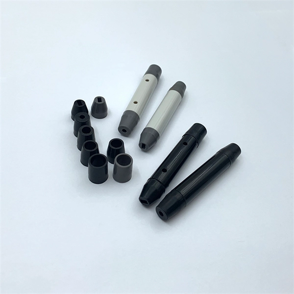
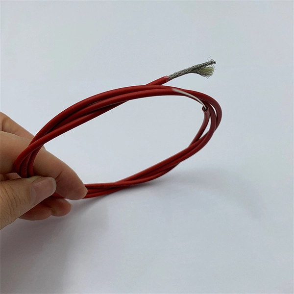
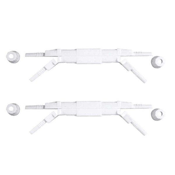
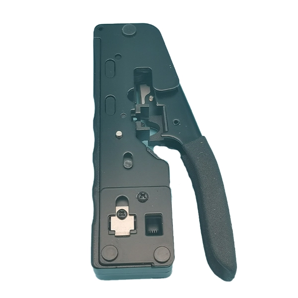
How to plug in a communication pigtail
Now that you have all the necessary tools and materials, you can start making an electrical pigtail. Here's a step-by-step guide to guide you through the process:Pigtail connections are most frequently used to ground a switch or electrical outlet and for electrical devices that need to connect to multiple circuit wires. They also come in handy to lengthen circuit wires that are too short to reach a device. A pigtail is composed of three strands of wire. Whether you're replacing an outlet or adding a new fixture, knowing when and why to use a pigtail can save you time and prevent potential hazards. Professionals often prefer this method because it isolates issues, protecting downstream circuits from cascading failures. Fortunately, there's a better way.
[PDF Version]
-
Which port should I plug the fiber optic cable into when changing the router
This cable must then plug into the dedicated Internet or Wide Area Network (WAN) port on your router. To connect your fiber optic cable to a router, ensure you have the following: Fiber optic modem (ONT): Most fiber connections require an Optical Network Terminal (ONT), provided by your ISP. This specialized equipment serves as the. Optical Network Terminal (ONT): Converts the optical signal from the fiber cable into an electrical signal that your router can use. Make sure to carefully insert the fiber cable into the proper port labeled “Fiber” or “GPON. Unlike coax jacks or phone jacks, which are often plates installed flat against the.
[PDF Version]
-
Where to plug the fusion splice splitter
Please use a dedicated three-wire grounded AC power line, AC / DC power adapter. When the adapter input cable is connected to AC220V, 50 / 60HZ power supply, the user must use an effectively grounded three-holes socket. In this comprehensive guide, we will delve into when and why you need to splice fiber optic cables, discuss how you can maintain cleanliness during the process, and walk you through the steps of fusion splicing, step by step. The guide covers everything from basic principles of fusion splicing to detailed procedures; it is intended to provide both newbies and professionals with the necessary knowledge and skills. A fiber fusion splicer is an instrument designed to permanently connect two optical fibers by fusing their ends together using heat. This process creates a seamless joint, allowing light signals to pass through with minimal attenuation. Failure to comply with any of the instructions or warning contained in the User's Manual is a direct violation of the design, manufacture and intende standard use of the instrument.
[PDF Version]
-
Relay protection aviation plug
Rated to MIL-DTL-5015 specifications, these connectors are compatible with other products that meet the same standard. They can withstand high-vibration applications and frequent connection and disconnection. Ideal for professional and personal projects. Relay Socket is a versatile component identified by BACS16W2A. This socket features a threaded stud mounting method, allowing for secure installation in various configurations. With a maximum overall length of 1. Explore our full line of molded components for aviation, including parts designed to meet common MIL/NAS. Please note, Aircraft Spruce ®'s personnel are not certified aircraft mechanics and can only provide general support and ideas, which should not be relied upon or implemented in lieu of consulting an A&P or other qualified technician. Aircraft Spruce ® assumes no responsibility or liability for any. Designed and manufactured by Aircraftplugs. 3 PINS NATO AN2551 standard plug, made of strong polycarbonate, registered plug.
[PDF Version]
-
Chad Fiber Optic Patch Cord Processing
We take you behind the scenes to show you the fascinating production process—from precision cable assembly to final packing! 🔹 Step-by-Step Production – See how high-quality fiber optic cables are carefully crafted. 🔹 Quality Checks – Learn about the rigorous testing to ensure. Fiber optic patch cords, also known as fiber jumpers, are essential components in high-speed data transmission networks. Their performance directly impacts signal quality, insertion loss (IL), and return loss (RL). patch cord making machine, fiber patchcord production. Prepare Tools and Consumables: Polish Machine, Polish Pad, Polish Film, Polish Jig, Polish Oil, Fiber Cutting Pen 1. Cutting Fiber After removing the ferrule from the oven, use a fan to blow the ferrule to cool it down.
[PDF Version]
-
Calculation of Fiber Optic Patch Cord Splice Points
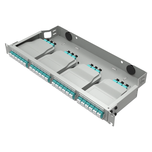
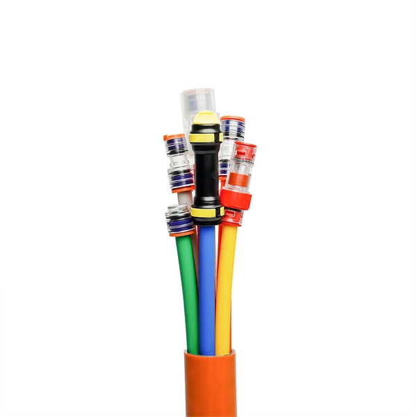
This calculator keeps optics, glass travel, and active forwarding separate so you can see where distance and delay enter the link. A fiber optic pigtail is a short length of optical fiber cable with a factory-terminated connector on one end and a bare, exposed fiber on the other. Unlike a patch cord—which has connectors on both ends—the bare fiber end of a pigtail is designed to be permanently spliced (either by fusion or. Estimate one-way and round-trip timing for fiber runs, optics, and active hops in home labs and backbone links. Direct point-to-point links with OS2 single-mode 1310 nm typically use 10 km+ of practical reach. 2 * Rear cable entries accommodate cables with diameter below 10mm. Splice loss depends on workmanship, fiber type, and method. Enter values based on recent OTDR traces, contractor QA records, or manufacturer. bers to be terminated from cable to cable or from cable to pigtail assemblies.
[PDF Version]
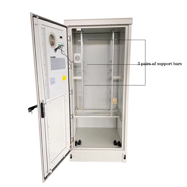
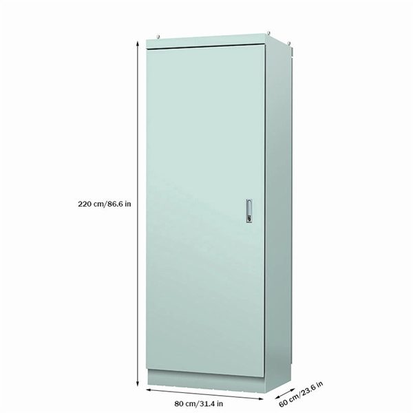
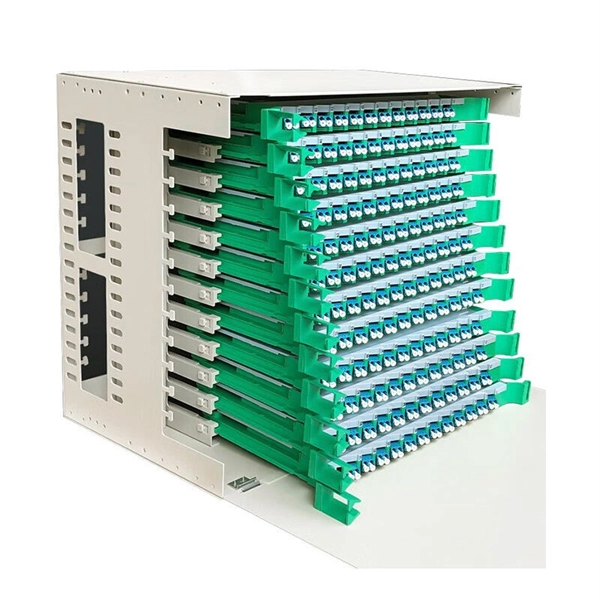
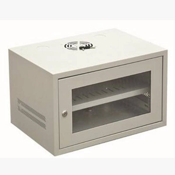
Telecom Racks & Cabinets
19-inch racks, wall-mount cabinets, open frames with high load capacity and seismic rating.
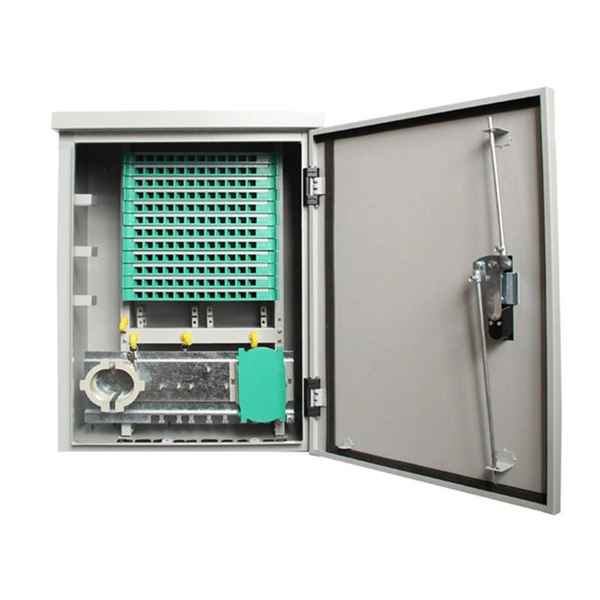
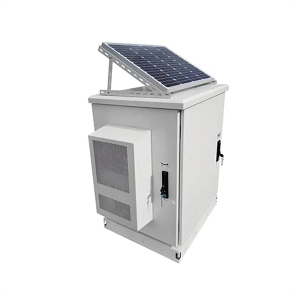
Outdoor Climate Cabinets
IP55/IP66 outdoor enclosures with integrated cooling/heating, -40°C to +55°C operation.
Smart PDUs & Power Distribution
Intelligent PDUs with remote monitoring, per-outlet switching, and environmental sensors.
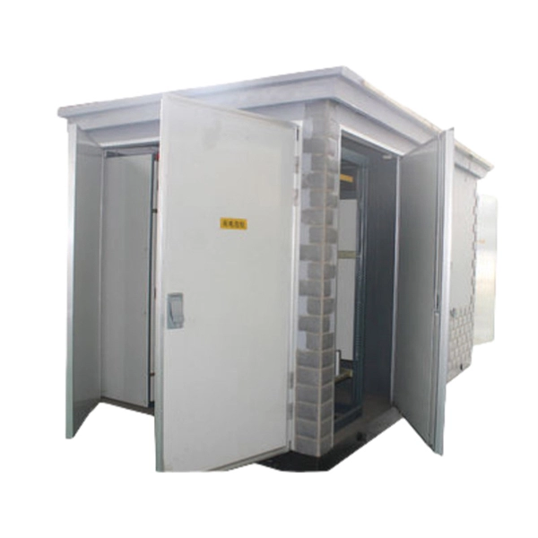
Shelters & Network Cabinets
Prefabricated telecom shelters, emergency comms shelters, and network cabinets with cable management.