-
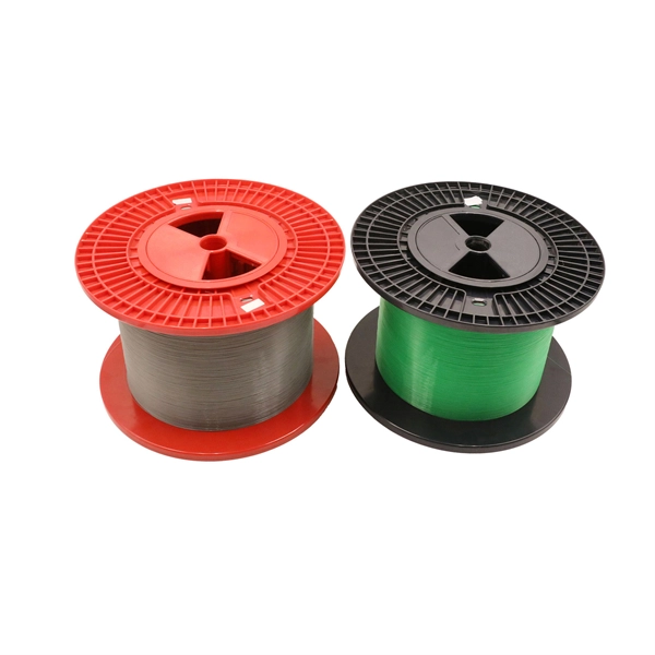
Fiber optic cables use cold splicing method
Principle of Optical Fiber Cold Splice Technology Optical fiber cold splice technology is based on the use of mechanical connectors to join two fiber-optic cables. These connectors are designed to align and join the fibers together in a precise and secure manner. Get the wrong connector type, the wrong polish, or skip proper fusion splicing technique—and you're looking at elevated signal loss, increased back reflection, and a. In this guide, we cover the basics of fiber optic splicing, how to perform splicing using two different methods, and finally some best practices to perform good fiber splicing. Ensure Your Splicing Tools are Clean – #2. This technique ensures high-performance data transmission and is essential in extending cable runs, repairing broken links, or establishing new network paths in data. Fiber optic cable splicing is the process of joining two fibers end-to-end to create a continuous optical path.
[PDF Version]
-

Fiber optic cold splicing in the factory
In this guide, you will find a chronological description of the fusion splicing process, the principal technical standards, and answers to the real-life questions network engineers and procurement teams may have. A fiber optic pigtail is a fiber optic cable with one end terminated with a factory-installed connector and the other end unterminated. As a result, the connector side can be connected to equipment, while the other side is fused in the case of fusion splicing and a mechanical connection in the case. Fiber optic joints or terminations are made two ways: 1) splices which create a permanent joint between the two fibers or 2) connectors that mate two fibers to create a temporary joint and/or connect the fiber to a piece of network gear. The main component inside is a precise v-groove. It is easier and faster to operate and saves time than welding with a. Fiber optics is the fastest and one of the safest ways to transmit information online. Fiber optic strands are ultra-lightweight and about as thin as human hair, and yet, they have more than eight times the pulling tension of a copper wire.
[PDF Version]
-
Is the failure rate of fiber optic cold connectors high
If you've ever stood in a data center cold aisle or a roadside splice closure, you know the truth: fiber doesn't fail in the middle of the cable. It fails where we touch it—where glass meets human hands, where theory meets dust, humidity, and haste. Understanding the common causes of failure and implementing preventive measures is essential to maintaining reliable networks and avoiding costly downtime. In this. Fiber optic patch cords are often treated as low-risk consumables, yet a large percentage of optical link failures originate at the patch cord level. Unlike backbone cables, patch cords are frequently connected, disconnected, bent, and handled by technicians, making them the most vulnerable. Fischer Connectors offers not only standardized products that operate within certain temperature ranges, e. Physical damage is one of the most frequent causes of fiber.
[PDF Version]
-
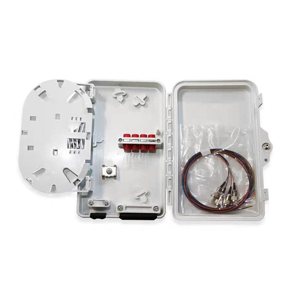
Does fiber splicing in a junction box count as a termination
Fiber optic joints or terminations are made two ways: 1) connectors that mate two fibers to create a temporary joint, patch between two cables and/or connect the fiber to a piece of network gear or 2) splices which create a permanent joint between the two fibers. A fiber optic termination box, often called an optical distribution frame (ODF) or fiber patch panel, serves as the endpoint where incoming fibers connect to devices or patch cords. It facilitates termination, protection, and organization of fiber connections, typically at the user end, such as in. When deploying fiber optic cabling, one of the most critical decisions is how to terminate the fiber—either by splicing or using connectors. Key Functions Typical Applications ZION FTB Highlights In essence: The Fiber Terminal Box is an end-user termination device for small-scale distribution. ■ What Is a Fiber. In this lesson, a long and very important one, you will learn about fiber splicing and termination.
[PDF Version]
-
Fiber optic cold connector transmits light
Summary : Winter weather generally has minimal impact on fiber optic cables since they transmit data through light rather than electricity, making them resistant to temperature-related signal loss. The time that light transmits in the optical fiber will also have loss, and this type of loss is mainly due to the transmission loss of the optical fiber and the splice loss at the optical fiber joint. While the fibers themselves are protected by an acrylic layer, the connectors joining each fiber can be vulnerable in harsh environments. In an era where speed and bandwidth are critical, understanding the principles behind. These strands, known as fibre optic cables, have revolutionised telecommunications because they transmit information using pulses of light. Unlike copper wires, which send electrical signals and suffer from resistance and interference, fibre optics offer orders of magnitude more bandwidth and.
[PDF Version]
-
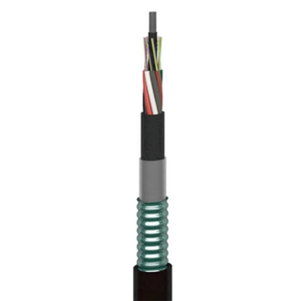
Russian Safe Fiber Optic Cable Splicing
(1) This section describes approved methods for splicing plastic insulated copper and fiber optic cables. Typical applications of these methods include aerial, buried, and underground splices. (2) American National Standard Institute/National Fire Protection Association (ANSI/NFPA) 70, 1993. (a) Except as covered in Bulletin 345-3, no loan funds shall be advanced for any product if any item to be included in the project is not included in the “List of Materials Acceptable for Use on Telephone Systems of RUS Borrowers,” RUS Bulletin 344-2. When new items of materials or equipment are. 7 CFR 1755. - Content Details - CFR-2011-title7-vol11-sec1755-200 7 CFR 1755., FTTH, FTTP, FTTM), splicing is essential for extending cables, repairing breaks, or connecting backbone and distribution lines. FO-VC2 JOINT USE - VERICAL MIDSPAN CLEARANCES 48. APPENDIX A - COVER SHEET / TOC 52.
[PDF Version]
-
1444 Fiber Optic Cable Splicing
Learn how to splice fiber optic cable using fusion splicing with this complete step-by-step guide. Includes tools, best practices, loss standards (ITU-T G. 652), cost analysis, and FAQs for network engineers and installers. Fiber optics is the fastest and one of the safest ways to transmit information online. Regardless of the type of fiber network you're deploying, be it for telecom, enterprise data centers, or smart city infrastructure, fusion splicing provides the benefits of. Executive Summary: A fiber optic pigtail is one of the most commonly specified yet least understood components in structured cabling. Done wrong, you'll be back.
[PDF Version]
-
What to do if fiber optic cold splices have high attenuation
When attenuation rises, you see reduced data speeds and higher error rates. Learn to use the OTDR to identify contamination, micro-bends, and poor splices, ensuring your 400G network links remain within budget. When a critical 400G link fails to establish or performs intermittently, the root cause is almost always excessive fiber optic attenuation. > You can solve this with simple steps. Clean Fiber Optic connectors often to stop dirt and dust. Dirt and dust can make. Fiber optic attenuation means signals get weaker as they move in optical fibers. Things like impurities in the fiber core and reflections at the core-cladding edge cause this drop. Reliable fiber optics depend on minimizing fiber signal loss for better network efficiency, data integrity, and longer transmission. This measurement helps determine the efficiency of a fiber optic system.
[PDF Version]
-
Acceptance Requirements for Optical Fiber Cable Splicing
IPC-A-640, officially titled “Acceptance Requirements for Optical Fiber, Optical Cable, and Hybrid Wiring Harness Assemblies,” provides acceptance criteria for cable and wire harness assemblies that incorporate optical fiber technology. The Contractor tasked to perform testing or splicing on any fiber optic cable will follow these testing standards to fulfill their contractual obligations. This testing. METR IBER MEDIA NET WORK Fiber Optic Cable Splicing, Testing and Acceptance Criteria for Contractors Version 1. Typical applications of these methods include aerial, buried, and underground splices. (2) American National Standard Institute/National Fire Protection Association (ANSI/NFPA) 70, 1993. d suppliers of electrical construction services. Unlike copper wire harnesses where a slightly imperfect crimp might still conduct electricity, a contaminated fiber end face or improper splice can completely block light transmission. The contractor submits test results. And then someone — usually someone who hasn't done this before — tries to figure out whether.
[PDF Version]
-
Trunk Fiber Optic Cable Splicing Full-Process Equipment Room
This guide explains what fiber cable splicing is, how it is performed inside a fiber enclosure, and best practices for achieving optimal performance. Regardless of the type of fiber network you're deploying, be it for telecom, enterprise data centers, or smart city infrastructure, fusion splicing provides the benefits of. Fiber cable splicing is a critical step in building reliable fiber optic networks. Every enclosure is built at our facility in Strafford, Missouri, using U. Fiber optic strands are ultra-lightweight and about as thin as human hair, and yet, they have more than eight times the pulling tension of a copper wire. The guide provides the complete workflow, covering safety precautions, tool selection, fiber preparation, fusion operation, quality control, and.
[PDF Version]
-
How much does fiber optic splicing and testing cost
Typical rates range from $75 to $180 per hour per technician, with on-site time often dominating the total. Hidden costs include traffic control, trench restoration, and post-repair verification testing. The "per splice" rate is the most. Users typically pay for fiber optic repair based on problem location, accessibility, and required restoration. Includes fusion/splice, testing, and basic materials. I usually bill T&M, but it works out to about $175-250 for setup/teardown per site and $4-7 per fiber for prep in a new tray in an existing case and splicing depending on if it's flooded or dry cable. Understanding these factors can help businesses and individuals budget effectively for fiber optic.
[PDF Version]
-

Oman Multimode Fiber Fusion Splicing Quotation
Get competing quotes from suppliers, lenders or both. SPEED MEETS PRECISION - Achieve flawless fiber splicing in just 9 seconds! LIGHTWEIGHT PORTABLE - Designed for on-the-go professionals—carry it anywhere! VERSATILE CONNECTIVITY - Seamlessly splice various optical fibers with ease. USER FRIENDLY INTERFACE - Bilingual instructions ensure everyone can. The new Single fiber optic Fusion Splicer of SUN Telecom SUN-FS930 is a small, compact and lightweight unit featuring the very latest in core alignment splicing technology. OF-800 Mini FTTX Fusion Splicer Features: 2. 5 inch LCD color display Small volume, light weight Suitable for science research. There are two primary methods of splicing fiber optic cables: fusion splicing and mechanical splicing. Each method has distinct characteristics and costs associated with it. *The prices on this table are only estimates, and are based on actual Fusion Splicer quotes submitted by KWIPPED Suppliers in the last 12 months. The main cost drivers are cable grade (indoor vs outdoor, riser vs plenum), fiber type (single-mode vs multimode), connectorization, and installation length. This guide presents cost ranges in.
[PDF Version]
-
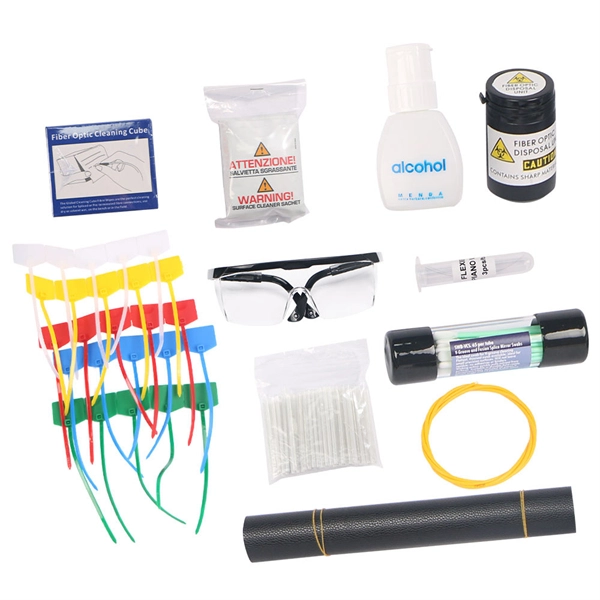
How to use fiber optic splicing trays
How do you use a splice tray? To use a splice tray, you must prepare your workspace, choose the right tray, prepare the fibers, install the fibers into the tray, seal the tray, and store it appropriately. Fiber cable splicing is a critical step in building reliable fiber optic networks. Whether in data centers, telecom rooms, or outdoor FTTx deployments, proper splicing inside a fiber enclosure ensures low signal loss, long-term stability, and easy maintenance. Splice trays play a crucial role in preserving the. In this guide, we cover the basics of fiber optic splicing, how to perform splicing using two different methods, and finally some best practices to perform good fiber splicing. Ensure Your Splicing Tools are Clean – #2. In the past, fiber optic splice trays were usually installed in a box that hung on the wall. more Skip the cable setup & start watching YouTube TV today for free.
[PDF Version]
-
What dB value is considered acceptable for optical fiber splicing
Acceptable splice loss in optical fiber is typically considered to be less than 0. What is the typical acceptable splice loss for single-mode fiber using fusion splicing? What is the acceptable splice loss for multimode fiber using mechanical splicing? How does fiber alignment affect splice loss? Why is cleaning the fiber important before splicing? What role does the cleaver play. Acceptable dB loss for fiber depends on the component you're measuring: a single mated connector pair should lose no more than 0. 5 dB per kilometer depending on the type and wavelength. The total. However, acceptable values depend on: * Project specifications * Link budget calculation * Network type (FTTH vs backbone) * Customer SLA requirements 🛠 Fusion vs Mechanical Splicing * **Fusion splicing** typically gives lower loss (0. * **Mechanical splicing** usually results in. The splice loss is measured in decibels (dB) and is influenced by various factors such as the quality of the splice, the alignment of the fiber cores, and the type of splicing technique used. 5 dB, while for multimode. For each connector, we usually figure 0. However, various factors, such as fibre cleanliness, core.
[PDF Version]
-
Fiber Optic Cable Splicing Success Rate
Fiber fusion splice —the gold standard—uses heat to meld glass ends, ensuring durability and low loss—e. 05 dB splice stays within a 17 dB budget for 10G. A practical guide to fiber optic splicing techniques, tools, and best practices from Richesin Engineering's field crew. Done right, it produces connections with less than 0. 1dB loss that will last the life of the cable plant. Essential for mending faults or scaling networks, splicing underpins the backbone of contemporary communications. In this comprehensive guide. Fiber optic pigtails are used to connect fiber optic cables using fusion or mechanical splicing. What is a mechanical splice? What is a fusion splice? Why splice? Fiber splicing is one way to join two optical fibers together so the light energy from one optical fiber can be transferred to another. In this article, we'll break down the two main ways to splice fiber optic cable, mechanical vs fusion, and walk through the tools, the real-world process, and what we've learned after moving fully to fusion.
[PDF Version]
Telecom Racks & Cabinets
19-inch racks, wall-mount cabinets, open frames with high load capacity and seismic rating.
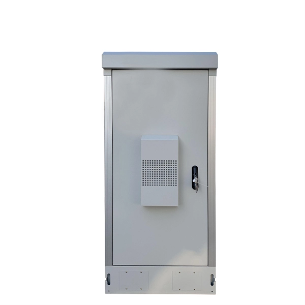
Outdoor Climate Cabinets
IP55/IP66 outdoor enclosures with integrated cooling/heating, -40°C to +55°C operation.
Smart PDUs & Power Distribution
Intelligent PDUs with remote monitoring, per-outlet switching, and environmental sensors.
Shelters & Network Cabinets
Prefabricated telecom shelters, emergency comms shelters, and network cabinets with cable management.