-
How to coil fiber optic cables in a fusion splice spool
Learn how to splice fiber optic cable using fusion splicing with this complete step-by-step guide. 652), cost analysis, and FAQs for network engineers and installers. In this guide, you will find a chronological description of the fusion splicing process, the principal technical standards, and answers to the real-life questions network engineers and procurement teams may have. The technique for removing the coating involves mastering the "steady, even, and quick" approach. The guide provides the complete workflow, covering safety precautions, tool selection, fiber preparation, fusion operation, quality control, and. With this in mind, we have prepared the ultimate guide on how to use a fusion splicer on fiber optic cables.
[PDF Version]
-
How to tie fiber optic cables to a fiber optic splice tray
Secure tight bufered cables using cable ties threaded through holes in the tray (Figure 5). IMPORTANT: Multiple pigtails may be secured with a single cable tie. Fiber cable splicing is the process of permanently joining two optical fibers end-to-end to allow light signals to pass through with minimal loss. Unlike fiber connectors, which can be plugged and unplugged, splicing creates a fixed connection that is typically more stable and has lower insertion. By following these detailed steps, the installation of your Fiber Splice Closure will be secure, organized, and maintained, ensuring high performance and longevity of your fiber optic network. Whether you're installing a new network, expanding an existing one, or. In this guide, we cover the basics of fiber optic splicing, how to perform splicing using two different methods, and finally some best practices to perform good fiber splicing. Ensure Your Splicing Tools are Clean – #2.
[PDF Version]
-
Blue Fiber Optic Tray
Clearview Blue is a five component tool-less system made up of a top cover, splice tray, buffer tube/ribbon slack storage, cable assembly tray and adapter plate. Parts snap together to support desired app.
[PDF Version]
-
Multimode fiber optic splice loss standard
For multimode fiber, the loss is about 3 dB per km for 850 nm sources, 1 dB per km for 1300 nm. 5 dB/km max per EIA/TIA 568) This roughly translates into a loss of 0. Splicing is required to create a continuous path for light transmission from one fiber to another. Two different methods exist for splicing fibers: Typical splice loss values (the measure of loss in optical power across the splice point) are usually lower for fusion splices (typically less than 0. 1. To be able to judge whether a fiber optic cable plant is good, one does a insertion loss test with a light source and power meter and compares that to an estimate of what is a reasonable loss for that cable plant. The estimate, called a "loss budget" is calculated using typical component losses for. Acceptable dB loss for fiber depends on the component you're measuring: a single mated connector pair should lose no more than 0. 75 dB, a fusion splice should stay under 0. 5 dB per kilometer depending on the type and wavelength. The Contractor must utilize the correct equipment and testing techniques to gain acceptance, or the work cannot be approved. Optical fiber splicing is a critical.
[PDF Version]
-
How to connect fiber optic cables without fusion splicing
In this article, you will learn how to splice optical fiber without using a fusion splicer, using alternative methods such as mechanical splicing, V-groove splicing, and glue splicing. Experts who add quality contributions will have a chance to be featured. What is a. Executive Summary: A fiber optic pigtail is one of the most commonly specified yet least understood components in structured cabling. Get the wrong connector type, the wrong polish, or skip proper fusion splicing technique—and you're looking at elevated signal loss, increased back reflection, and a. To connect or repair optical fibers, you need to splice them, which means joining two fiber ends together. Splicing fiber helps light signals move easily, ensuring your internet connection remains reliable. This article explains when.
[PDF Version]
-
Does a poorly prepared fiber optic tray have any impact
Fiber optic cables transmit data using light, which makes them sensitive to bends, contaminants, and poor connections. A single error can cause: Signal Degradation: Even minor bends or cracks can lead to significant data loss. Increased Costs: Reworking installations can double. Fibre optic splicing trays are an essential part of manipulating and ordering optical fibers inside a network structure. Since the need for higher data rates and effective communication gets more robust, the utilization of optical fibers has become increasingly widespread across multiple spheres of. Engineers often joke that fiber is both incredibly tough and ridiculously fragile—it can transmit terabits across continents, yet a speck of dust on the connector can bring down a critical link. What Can Happen? · Failed communications modules in the equipment Underground cable dig-ups Aerial cable damage from gunshots and a squirrel. In my case, the wide-radius corners allow reducing signal loss.
[PDF Version]
-
Fiber optic cable tray fixing for subway
To use these holes for fiber installation, first use a mini hand drill to drill U-shaped holes as pre-outlined in the Cable Tray Base. It covers the most common components used in a fiber tray installation, but each installation is different and the unique circumstances and requirements of any given installation environme qualified technicians. For the purposes of this guideline, a qualified technician is. There are 5 undrilled U-shaped Fiber Cable Input Holes reserved for flexible fiber installation. This comprehensive guide investigates the most frequent wire management challenges faced in real-world setups and demonstrates how the correct cable tray accessories may address them. Its basic components include: straight grooves, horizontal and vertical elbows, optical fiber outlets, connectors and supports.
[PDF Version]
-
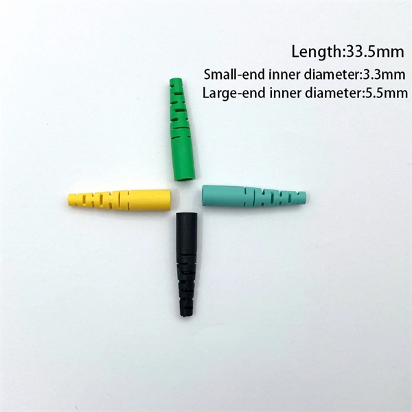
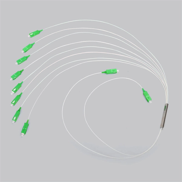
Calculation of Fiber Optic Patch Cord Splice Points
This calculator keeps optics, glass travel, and active forwarding separate so you can see where distance and delay enter the link. A fiber optic pigtail is a short length of optical fiber cable with a factory-terminated connector on one end and a bare, exposed fiber on the other. Unlike a patch cord—which has connectors on both ends—the bare fiber end of a pigtail is designed to be permanently spliced (either by fusion or. Estimate one-way and round-trip timing for fiber runs, optics, and active hops in home labs and backbone links. Direct point-to-point links with OS2 single-mode 1310 nm typically use 10 km+ of practical reach. 2 * Rear cable entries accommodate cables with diameter below 10mm. Splice loss depends on workmanship, fiber type, and method. Enter values based on recent OTDR traces, contractor QA records, or manufacturer. bers to be terminated from cable to cable or from cable to pigtail assemblies.
[PDF Version]
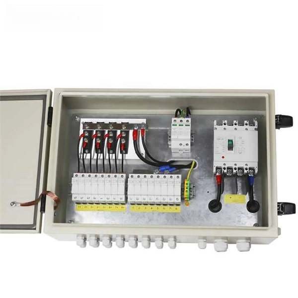
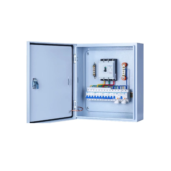
Telecom Racks & Cabinets
19-inch racks, wall-mount cabinets, open frames with high load capacity and seismic rating.
Outdoor Climate Cabinets
IP55/IP66 outdoor enclosures with integrated cooling/heating, -40°C to +55°C operation.
Smart PDUs & Power Distribution
Intelligent PDUs with remote monitoring, per-outlet switching, and environmental sensors.
Shelters & Network Cabinets
Prefabricated telecom shelters, emergency comms shelters, and network cabinets with cable management.