-
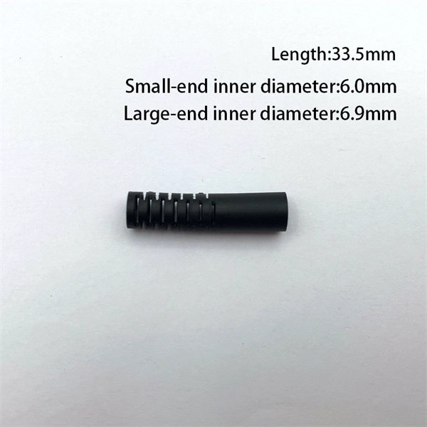
Fiber Optic Cable Installation Completion Inspection
Routine Inspection: Regularly check for loose connections, wear, and cable integrity. The Fiber Optic Association, Inc. (FOA) was founded in 1995 to help develop the workforce to build the fiber optic networks to support a rapid expansion in communications and the Internet. They define a minimum baseline of quality and workmanshi for installing electrical products and systems. NEIS® are intended to be referenced in contrac documents for electrical construction ation or liability to users of this publication. 1) The other portion of a good physical contact between the connectors ferrules is the absence of any type of. Fibre Optic Cleaver and splicer for precision cutting and joining. Following the steps in this document will ensure all cable installation actions are performed properly according to recommended standard practices and the. National Electrical Installation StandardsTM are designed to improve communication among speci-fiers, purchasers, and suppliers of electrical construc-tion services.
[PDF Version]
-
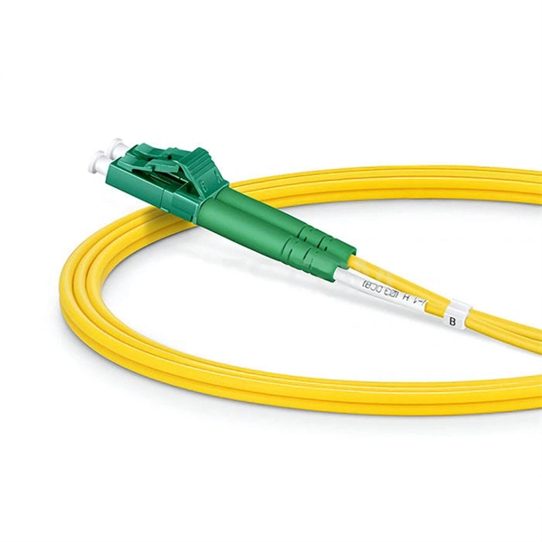
Fiber Optic Patch Cord End Face Inspection Techniques
Endface inspection focuses on the visible quality of the polished fiber surface and surrounding ferrule area. You use a fiber microscope or automated inspection scope to check for contamination, pits, chips, cracks, and scratches. Even a small dust particle or scratch on the endface can increase insertion loss, reduce return loss, and introduce random link instability. In FTTH, ODN, and data center environments, you rely on consistent. That is why relying on International Electrotechnical Commission (IEC) industry standards and innovative inspection equipment is the most reliable way to ensure automatic, consistent, and repeatable certification of fiber cleanliness based on specific acceptance criteria. Fiber Contamination, Cleaning and Inspection. This article outlines the specific. 📦 For purchasing, use the RP Photonics Buyer's Guide for fiber endface inspection. It provides an expert-curated supplier directory, buyer-focused technical background information, and structured selection criteria to support professional procurement decisions. Fiber optics is generally quite.
[PDF Version]
-
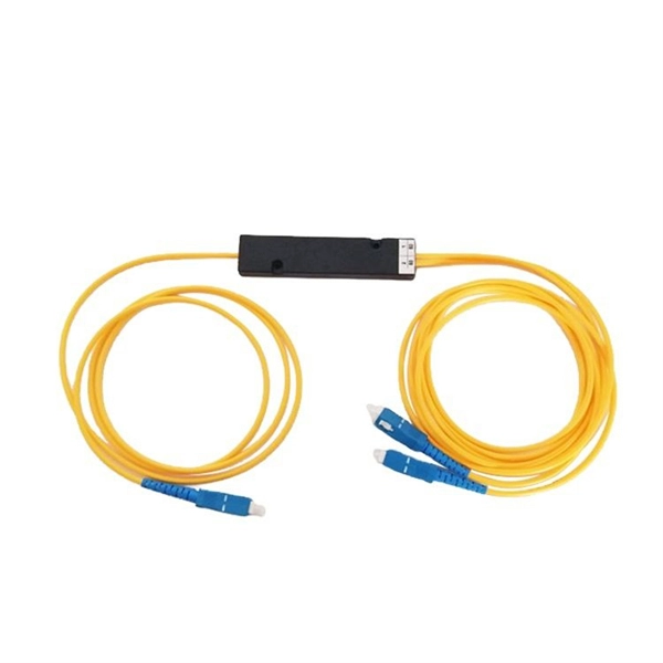
Monitoring fiber optic cable transmission power
Fiber optic sensing enables TSOs to monitor overhead power lines accurately for hundreds and thousands of kilometers in real-time – without adding sensors on lines or towers. It achieves this by providing conti.
[PDF Version]
-
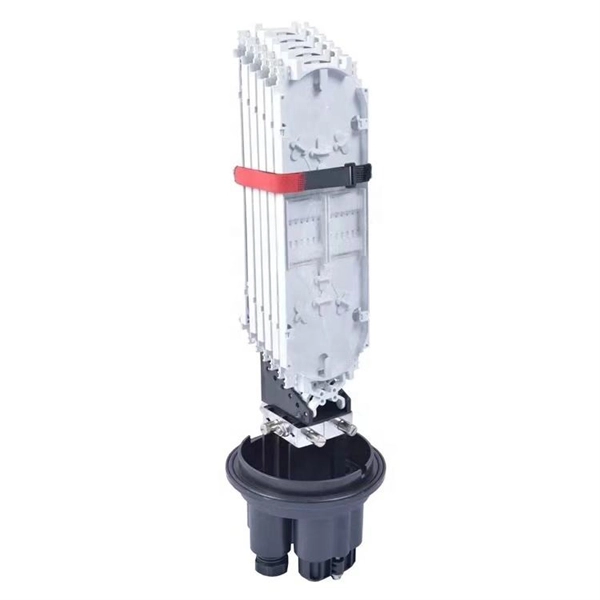
Does the fiber optic terminal box need to be connected to a power cable
Once your network box or gateway has been properly connected to your fiber terminal, connect the power cord to the network box and then plug it into a power outlet. As with a router, the lights should turn on and start blinking, eventually turning a solid color. A fiber pigtail is a specific hardware connection used for cable termination. Thus, a fiber termination box is used to terminate the optical fiber. The terminal box sits at the premises edge: in a hallway cabinet, apartment wall plate, small office IDF, or MDU corridor. It terminates the drop cable and presents standardized adapter ports (commonly SC/APC for FTTH) for a patch cord to the ONT/ONU. Before. A Fiber Termination Box, also known as an optical termination box (OTB), is a compact, specialized enclosure designed for the organization, termination, splicing, and protection of fiber optic cables. Connect your device to the network box. These steps are very similar to self-installing other types of internet, but with a few important differences.
[PDF Version]
Telecom Racks & Cabinets
19-inch racks, wall-mount cabinets, open frames with high load capacity and seismic rating.
Outdoor Climate Cabinets
IP55/IP66 outdoor enclosures with integrated cooling/heating, -40°C to +55°C operation.
Smart PDUs & Power Distribution
Intelligent PDUs with remote monitoring, per-outlet switching, and environmental sensors.
Shelters & Network Cabinets
Prefabricated telecom shelters, emergency comms shelters, and network cabinets with cable management.