-
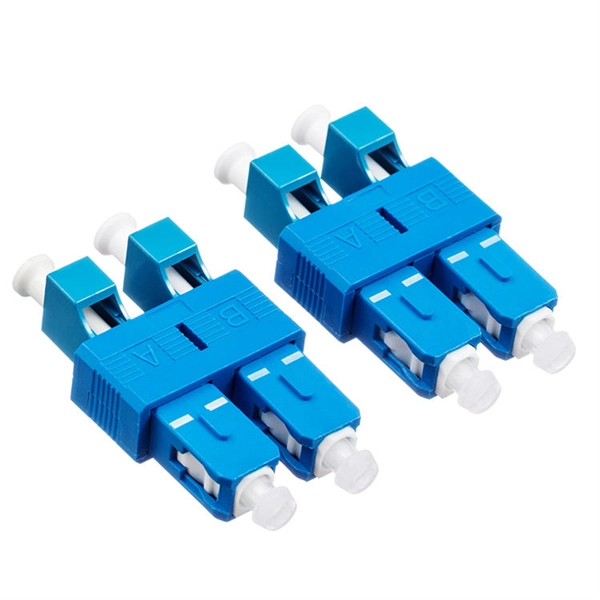
How to tell the front from the back of a fiber optic patch cord
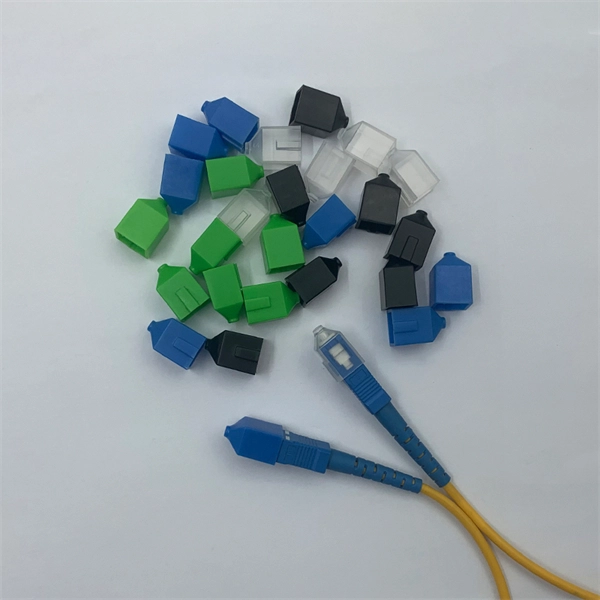
The ferrule end face of the patch cord is ground into different structures. PC, APC, and UPC are three different ferrule polishing methods, representing the structural differences of the front face of the ceramic ferrule. As shown below, the ferrule is the housing for the bare end of an optical. At ZION Communication, we design and manufacture a full range of fiber patch cords for: This guide will help you quickly understand the main types of fiber patch cords and how to choose the right solution for your project – and how ZION can support you with stable quality, flexible customization. Here at Fiber Optic Center, we believe it's important to introduce engineers and technicians to various aspects of the production process to manufacture high-performance, world-class fiber optic cable assemblies. Ideally, your finished fiber optic cable assembly will meet all relevant international. Fiber optic patch cords, also known as fiber optic patch cables or fiber jumpers, are indispensable components in modern optical networks. Fiber optic patch cables are found almost everywhere; cable television networks (CATV), data centers, computer networks, and telephone networks.
[PDF Version]
-
What is a fiber optic transceiver module for a switch
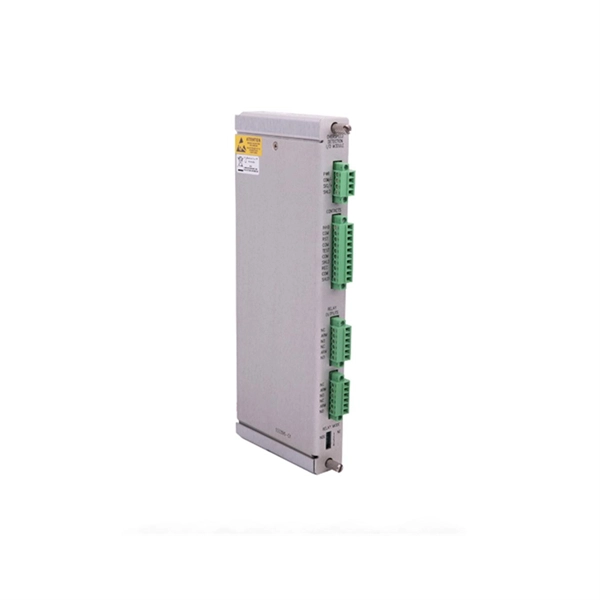
An SFP module is a small, pluggable optical transceiver that fits into the SFP port of a networking switch or other device. Sometimes, it is known as the mini-GBIC (gigabit interface converter) or SFP transceiver. However, some technicians may also mistype it as an SPF module . A fiber transceiver is the pluggable interface module that performs this conversion, enabling Ethernet devices to use different fiber types, reach different distances, and upgrade link speeds with minimal disruption. It serves a dual purpose — transmitting electrical signals as light pulses and receiving light pulses to convert them back into electrical form. The “S” in SFP represents Samll, the letter “F” stands for Form-factor, and “P” stands for Pluggable.
[PDF Version]
-
How to connect fiber optic cable to the optical transceiver
Remove protective caps from optical fiber connectors, insert optical fibers into the optical transceiver, and connect the fiber to the peer device. Ensure that the Tx and Rx ports are correctly connected. This guide explores the essentials of SFP connectivity, installation best practices, and how Weunion's. Proper connection of fiber optic cables is essential to harness these benefits fully, as even minor errors can lead to significant performance issues like signal loss. To connect a fiber optic cable to SFP optical module, first ensure the SFP is fully inserted into the network port until it "clicks", then remove the dust caps from both the SFP and the LC fiber optic connector. The USG supports both 1 Gbit/s, 10 Gbit/s, and 40 Gbit/s optical modules. To learn more about the types of fiber optic connectors, click here: Types. In this article, we will guide you through the process of connecting optical fiber cables, step by step.
[PDF Version]
-
How to configure a fiber optic transceiver switch
This quick yet practical demonstration dives into the installation, configuration, and traffic monitoring of SFP optical and twisted-pair transceivers. SFP Transceiver Module – Choose the appropriate module based on your network requirements (e. If you're looking to learn how to configure fiber optics on a Cisco switch, it's important to first configure the switch settings so it's ready for fiber optics. These transceiver modules are hot-swappable input/output (I/O) devices that plug into 100BASE, 1000BASE and 10GBASE ports (for SFP+), which connect the module. A newly added feature on some Microchip Gigabit Ethernet switches is a serial Gigabit media independent interface (SGMII) for one of the ports.
[PDF Version]
-
What is the fiber optic cable on the back of the router
It is a 'standard' single-mode fiber cable with an SC-APC connector at the end. You can't 'really' connect it directly to a random consumer router in most cases - it's meant to go into an optical fibre device. We provide bulk fiber patch cords, ONTs, and pre-terminated cables for large-scale FTTH deployments. [Get a Project Quote] Are you ready to unlock the blazing-fast potential of fiber optic internet? The process to connect fiber optic cable to router requires careful attention to detail, but I'll. A fiber cable (drop) is run from a nearby terminal that could be either a pole or an underground box) to your home. it is called what you called it. Why do you want to use your router instead of the one the ISP gave you? That is clearly not an option. Made of strands of glass or plastic thinner than a human hair, the cables transmit data as pulses of light.
[PDF Version]
-
How far should the power fiber optic cable be from the house
For indoor fiber optic cables, the maximum pulling distance typically ranges from 100 to 200 meters. The shorter distance accounts for the lower tensile strength and the need for gentle handling to avoid damage to the delicate fibers. This composite cable combines the distance and bandwidth capabilities of singlemode fiber with the power-carrying capability of 14-AWG copper conductors. by Jeanna Deese and Chris Rivas Power over Ethernet—it may be an old concept, but new applications continue to be identified that are redefining. Unlike Power over Ethernet (PoE), which is limited by copper cable characteristics, PoF leverages optical fiber to overcome distance, electromagnetic interference, and safety constraints. It depends on multiple. Need some clarification about NEC 770. Is this 300 mm separation from the center of the power cable to the center of the fiber optic cable, or is it from the side of the power. The pulling distance of fiber optic cables depends on several factors, including the type of cable, installation environment, and pulling techniques. Understanding these factors is crucial for planning and executing a successful installation.
[PDF Version]
-
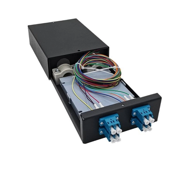
How to install the coupler into the fiber optic box
Splice the Pigtail:Fusion-splice incoming fiber to pigtail inside the box. Test:Verify light levels: -27 dBm to -8 dBm (GPON ideal). If you work with single‑mode optical networks—FTTH, PON, CATV, 5G fronthaul—you will run into the SC/APC fiber optic adapter (sometimes called an SC/APC coupler) almost immediately. This small, inexpensive component is critical for aligning and mating two SC/APC connectors while preserving low. Fiber optic adapters, also known as couplers, play a crucial role in fiber optic networks by providing a connection point between two fiber optic connectors. A correct installation creates a low-loss, reliable connection essential for high-speed data transmission. While fiber optics enable speeds and distances copper can't match, the system's performance hinges. Keeping this page as a placeholder for now. Have any questions? Talk with us directly using LiveChat. Covers mounting, splicing, routing, labeling, and testing for indoor/outdoor use. A. ⚡ Level Up Your Fiber Skills – Join the One Up Techs Skool 👉 https://www. Most techs struggle because they: ❌.
[PDF Version]
-
How are fiber optic cables melted
It works by applying heat to the ends of the cables, causing them to melt and fuse together. This process creates a strong and reliable connection that can withstand environmental stresses and vibrations. How to melt indoor optical fiber optic cables,It is important to properly melt indoor optical fiber optic cables when splicing or terminating them to ensure that the connection is strong and reliable. Be extremely careful with the oven! NOTE: Paper catches fire at 451 degrees F, so don't rest anything. This virtual hands-on page will take you through the steps involved in the process. If you have your own equipment, do the recommended exercises. And tools used for fiber fusion: fusion splicer; fiber cleaver; cable stripper; fiber optic stripper; alcohol;. Thus, the conjugation of high power propagation and tight bending, resulting from the actual FTTH infrastructures, is responsible for fibre lifetime reduction, mainly caused by the local increase of the coating temperature.
[PDF Version]
-
What tools are needed for fiber optic cable attachment
Complete tools and materials checklist for fiber optic technicians: fusion splicers, OTDR, power meters, safety equipment, and work-specific consumables. Let's take a look at the common types of tools you may encounter in an installation. If you're just starting out, use this as a jumping off point to see how each tool works. Kevlar scissors are specifically designed to cut through Kevlar or aramid yarn strength members in fiber optic cabling. Unlike copper cabling, optical fiber requires precise handling, clean end faces, and accurate measurement to avoid signal loss and performance degradation. Installation tools include some big hardware like bucket trucks, trenchers, cable pullers or plows. The need for these will be established early in the planning stages.
[PDF Version]
Telecom Racks & Cabinets
19-inch racks, wall-mount cabinets, open frames with high load capacity and seismic rating.
Outdoor Climate Cabinets
IP55/IP66 outdoor enclosures with integrated cooling/heating, -40°C to +55°C operation.
Smart PDUs & Power Distribution
Intelligent PDUs with remote monitoring, per-outlet switching, and environmental sensors.
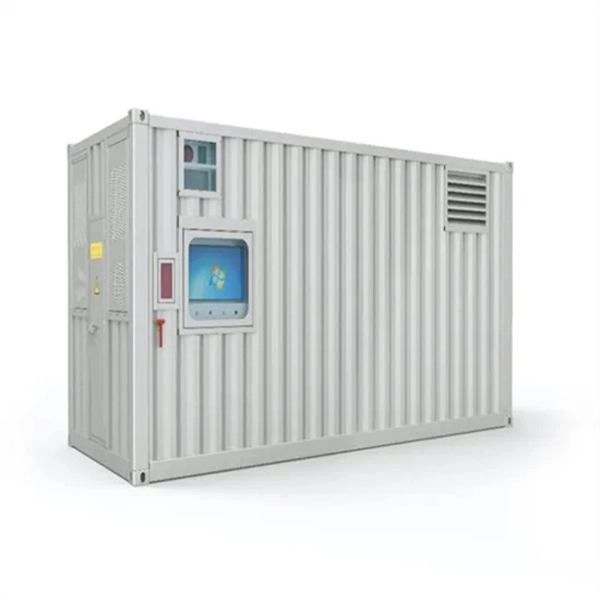
Shelters & Network Cabinets
Prefabricated telecom shelters, emergency comms shelters, and network cabinets with cable management.