-
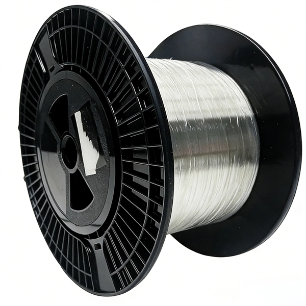
Belarusian large-core optical fiber 1310nm
In this article, we explore the key characteristics, common applications, and important comparisons related to 1310nm optical modules. Used for medium-distance links in city networks. As part of the O-band (1260–1360 nm), it balances low dispersion, stable performance, and cost efficiency. This makes it widely adopted in data centers, enterprise backbones, and metro access. The product features an SFP+ package with an LC connector, a 1310nm DFB laser with a PIN photodetector, and supports up to 20km transmission on SMF with power dissipation under 1W. Or It is also suited for analog fiber transmission. Pricing (USD) Filter the results in the table by unit price based on your quantity. A. 10GBASE-LRM SFP+ Transceiver Module 1310nm 220m - FS. com FS United StatesFREE SHIPPING on Orders Over US$79 Contact Us United States / $ USD Sign in Sign up Search Recent Searches Change FREE SHIPPING on Orders Over US$79 United States HomeOptical Transceivers10/25/40/100G. SFP+, 1310nm, LR SMF 10km, 10G DDM, Corning 1LAN-SFPP-10GB-LR Compatible Integra manufactures the highest quality SFPP transceivers in the industry, designed to be 100% interoperable with all OEM platforms.
[PDF Version]
-
How to connect a two-core fiber optic switch
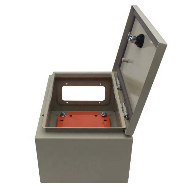
Most modern fiber-enabled network switches require an SFP transceiver module featuring a duplex (two strand) multimode OM3 or duplex single mode OS2 connection with LC connectors. Direct attach cables with pre-terminated SFP connections may also be used. Download the. In this article, we'll explain how to connect multiple Ethernet switches using fiber optic cables and the equipment required for this to work. Fiber provides: Increased internet signal bandwidth. (attached is the image here with) I see that the 2960 has 2 SFP ports each port of each switch. “Can I join two fiber cables inside a cabinet?” The answer is yes—but only if done the right way.
[PDF Version]
-
Will the light on the optical module illuminate when the fiber optic cable is plugged in
The LED status will not change when only the SFP module is plugged in. The LED will only light up when all connections are properly established and functioning correctly. When the connection does not work as expected after we set it up according to the Installation Guide, we need to do some troubleshooting. Should both Fiber SFP modules show a laser light in one of the two (duplex) receptacles? I followed this forums advice and ran some fiber in the conduit to a new detached garage. I had tested the fiber before running it to make sure it was working. The simplest way to test an SFP transceiver is with the FiberLert™ live fiber detector, which lights up and beeps when placed in front of an active fiber or port. ) does not receive a good signal from Switch A (Tx). The light from the end of the fiber is coupled to a receiver where a detector converts the light into an electrical signal which is then conditioned properly for use by. Looking at the SFP from the LC coupler, the left side is the light transmitter, the right side is the light receiver. An optic cable is composed of 2 joined optic fibers.
[PDF Version]
-
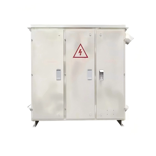
What are the benefits of lightning protection for optical fiber lines
Implementing lightning protection strategies such as surge protection devices, grounding systems, lightning rods, and proper cable design can help safeguard fiber optic cables and the networks they support. Lightning-induced surges can travel through power lines, telecommunication lines, or nearby metallic structures and pose a. Lightning protection is one of the key reasons for utilizing fiber optics. Unlike copper wire, the fiber itself is made from dielectric (non conducting) materials, cannot conduct electrical current, and is immune to EM radiation. Telecommunication equipment and communication lines located at or. Although the signals in fiber cables are optical signals, most of the outdoor optical cables using reinforced cores or armored optical cables are easy to get damaged under lightning because of the metal protective layer inside the cable. Since the lightning. It is well known that optical fiber has no electrical conductivity and can prevent from impact current.
[PDF Version]
-
Does the fiber optic bus have a switch
One key component of a fiber optic network is the fiber optic switch, which plays a critical role in managing data traffic and enabling efficient communication. Fiber optic technology is widely recognized for significantly advancing modern networking by enabling high-speed, low-latency, and interference-resistant communication across various applications. Fibre Channel is primarily used to connect computer data storage to servers in storage area networks (SAN) in commercial data centers. Fibre Channel networks form a. Both of these systems can be made much more robust by the use of a fiber optic bypass switch at each node. Figure 2 shows how such a switch operates. Light coming into the switch is routed to the receive port. What Is a Fiber Optic Ring Network? A fiber optic ring network is a physical or logical network topology where devices (usually switches) are connected in a closed-loop using fiber optic cables. Fiber optic switches offer numerous advantages over traditional.
[PDF Version]
-
Fiber optic fault breakpoint in optical time domain reflectometer
These reflections indicate splices, bends, breaks, and other faults. The OTDR trace provides a visual representation of these events, allowing technicians to pinpoint and address issues. The launch pulse appears as a large initial spike on the OTDR trace. Enter the Optical Time-Domain Reflectometer (OTDR) —a powerful tool for diagnosing, testing, and maintaining fiber optic cables. This guide dives deep into OTDR technology, its applications, and how it integrates with modern components like optical transceivers. We improve the level of equipment, but also by implementing fine operations can. OTDR testing analyzes fiber optic cable performance from end to end by testing components along the cable, including connection points, bends, and splices. Proper interpretation of OTDR trace results is crucial for efficient troubleshooting. Configure your OTDR correctly by setting the right.
[PDF Version]
-
What are the functions of an optical fiber communication control board
Their primary function is to directly boost optical signals without the need for optical-to-electrical conversion, thus preserving signal integrity and extending transmission distances. The diagram above shows how electronic input signals get transformed into light pulses, travel through a fiber optic cable, and are converted back into. Often, optical fiber communication plays a significant role in the development of telecommunication systems with high quality and speed. Nowadays, optical fiber applications majorly involve telecommunication systems with an inclusion of internet and local area networks (LAN) to achieve high. Using fiber optic control circuits provides electrical isolation for safety in hazardous environments. Because optical cables carry no current they are safe to use in explosive environments and eliminate the hazards of short circuits in metal wires and cables.
[PDF Version]
-
Huawei 5737 switch optical port
A 10GE SFP+ Ethernet optical port supports auto-sensing to 1000 Mbit/s. It sends and receives service data at 1000 Mbit/s or 10 Gbit/s. An active optical cable (AOC) is a fixed-length optical fiber with optical modules at both ends. Table 10-3 lists the models and attributes of. Optical modules are widely used in switches, network interface cards (NICs), routers, and other communication devices. During use, reading optical module information helps understand its real-time operating status, enabling faster troubleshooting of link abnormalities. The following uses the. Taking the Huawei 5700 series switches as an example, the commands to view optical module information are as follows: Transceiver Type :1000_BASE_SX_SFP Connector Type :LC Wavelength(nm) :850 Transfer Distance(m) :300(50um),150(62. Issue 01 (2019-06-28) Copyright © Huawei Technologies Co. It is used with a ground cable.
[PDF Version]
-
How to separate the fiber cores of OPGW24-core optical cable
Removing the aluminum strands and outer layers of the OPGW cable exposes the fiber optic cores 7, which is essential for proper termination. Use a file to smooth any sharp edges after removing the aluminum strands 8. Carefully separate the metal loose tubes without damaging. Proper termination of OPGW cables involves precise steps like careful handling 3, removing outer layers, cleaning fibers, and securing with clamps. In the construction of electric power dedicated communication network, the number of optical fibers used is usually 12 to 24 cores. With the continuous expansion of system capacity according to new business requirements, the number of cores is gradually increasing, and individual line sections have. out this step, cut a small piece of pipe, about 2 feet, from the free end of the cable and practice cuttin of the cable. While holding the cable, pull the optical units completely out of the pipe by pullin toward the tower. What is Fiber Optic Splicing and Why is it Needed? – #1. First, a heat-shrink tube is placed over the OPGW cable.
[PDF Version]
-
Price of optical fiber transmission cable engineering
Costs of fiber optic data transmission run at $0. 25/TB per 1,000km to earn a 10% IRR on constructing a cable with $120 per meter of capex. Main cost drivers include cable grade (indoor vs outdoor, armoured), distance, and labor for trenching, splicing, and termination. This guide presents ranges in USD and practical price estimates to help. Fiber optic cables consist of multiple fibers, each designed for high-speed data transmission. This data fiber breaks down the costs of data transmission from first principles, across capex, utilization. Since early 2026, the fiber optic cable price has been rising at an extraordinary pace. In preparing this second edition of the Fiber Deployment Cost report, Cartesian gathered inputs from a wide variety of firms building.
[PDF Version]
-
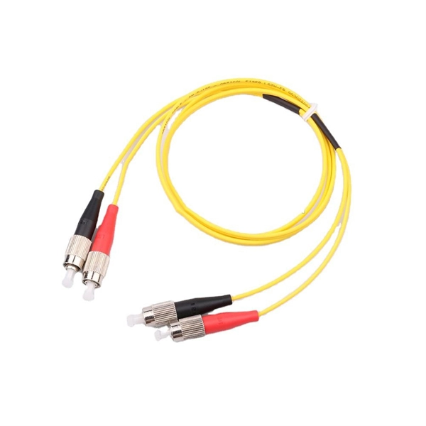
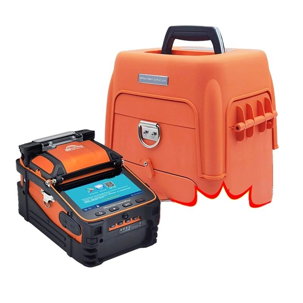
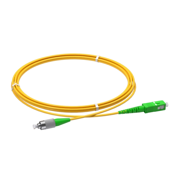
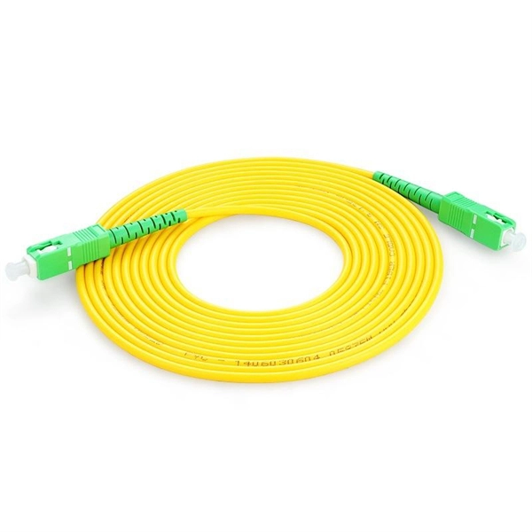
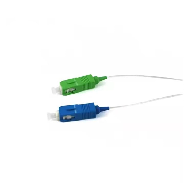
How to make a cold joint for double-wire optical fiber
In this video, we will learn how to joint two Fiber Optic Cables together or Fiber Optic Cable splicing #fiber #fibercable #fiberlaser #fibersplicing #fiberc. Fiber optic joints or terminations are made two ways: 1) splices which create a permanent joint between the two fibers or 2) connectors that mate two fibers to create a temporary joint and/or connect the fiber to a piece of network gear. Either joining method must have three primary characteristics. It is used to connect optical fiber or optical fiber butt pigtail, which is equivalent to making a joint (fiber butt pigtail refers to the butt joint of the fiber core of the optical fiber and the pigtail instead of the pigtail head mentioned in the former), and is used for this kind of cold. At the heart of any robust fiber optic network lies a crucial process: Preparing a fiber cable for termination of a connector or splice. Two types of splices are used in fiber optic cabling one is Mechanical the other is Fusion. What is Fiber Optic Splicing and Why is it Needed? – #1.
[PDF Version]
-
How do I switch the fiber optic cable to red light source mode
Turn on the optical visual fault locator. Most VFLs have a button or switch to turn on the light. You should see a visible red light coming from the fiber. Pay close attention to areas where the light is leaking or where it seems. A VFL is used to detect faults, breaks, or bends in fiber optic cables by emitting a bright red light that is visible even through the fiber's jacket. The button at the top of the device (with a red ring around it) is the on-off switch. This cable continuity tester helps find breaks in cables, connectors and splices. Compatible with. VFL usually uses red visible light (635-650nm) laser light source, and the optical output power of the laser is usually 1mW or less. You can see red light with the naked eye, but due to the high light output power, you should remember not to look directly at the output of the VFL. Using a VFL to diagnose issues can save time and cost when diagnosing an.
[PDF Version]
-
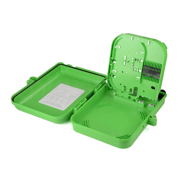
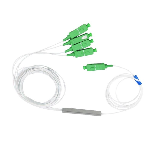
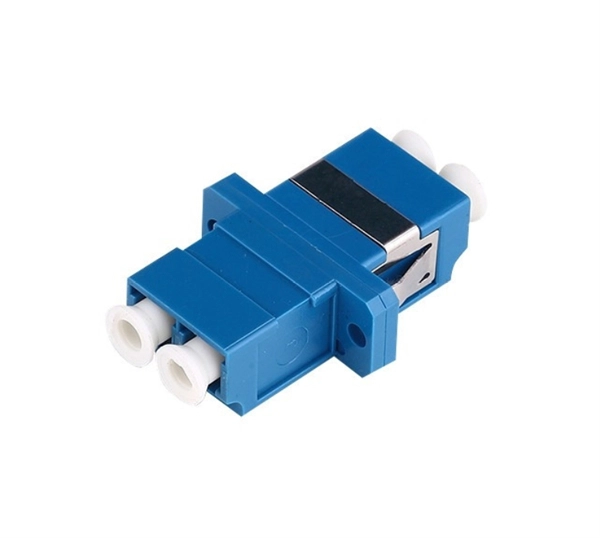
Does a fiber optic splitter need to be used at both ends of the optical fiber
A fiber-optic splitter, also known as a, is based on a of an integrated waveguide power distribution device, similar to a The system uses an optical signal coupled to the branch distribution. The splitter is one of the most important in the link. It is an optical fiber tandem device with many input and output terminals, especially applicable to a passive optical network (,,,.
[PDF Version]
-
The maximum distance of long-distance optical fiber cables
Max Length: Up to 100 kilometers (62 miles) or more without needing signal boosters or amplifiers. Usage: Single-mode fiber is ideal for long-distance communication, such as connecting cities or telecommunications over vast regions. The maximum transmission distance varies significantly between fiber types, with single mode fiber offering substantially greater range than multi mode fiber alternatives. Single mode is typically used for. The more power coupled into the fiber, the longer the transmission distance. Single-mode. The maximum reach of a fiber optic cable is not a property of the cable alone — it is the result of a balance between the link attenuation and sensitivity of active equipment A single OS2 cable can carry 1 Gbps over 100 km with suitable modules, or only 10 Gbps over 10 km with standard modules.
[PDF Version]
-
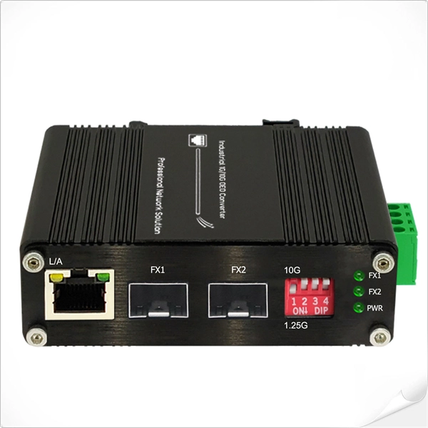
Test Report of Remote Monitoring Type Industrial-Grade Optical Switch
List of Attachments (including a total number of pages in each attachment): ATTACHMENT 1: National differences ATTACHMENT 2: Photo document Summary of testing: The product covered by this report has been tested and complies with the applicable requirements of this standard. The RFTS-400 modular platform design incorporates an Optical Control Module (OCM) and Optical Switching Modules (OSM) that support fiber monitoring expansion from 8 to 108 ports in the 1U rack. ONMSi is a remote fiber test system that scans the fiber. The Adaptive Fiber Test Head lies at the core of the VIAVI optical network monitoring system (ONMSi). Called “purpose-built” commercial components, these switches combine the lower cost of off-the-shelf components with DeltaV specific software and features. Part of EXFO's solution for remote fiber testing and monitoring (RFTM), the RTU-2 is a test unit that is remotely controlled via EXFO's central fiber monitoring system (FMS). It is a modular unit, hence allowing for flexibility and scalability. Intelligent OTDR-based solution for testing and monitoring fiber links (P2P and PON) from buildout to maintenance.
[PDF Version]
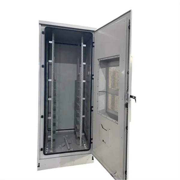
Telecom Racks & Cabinets
19-inch racks, wall-mount cabinets, open frames with high load capacity and seismic rating.
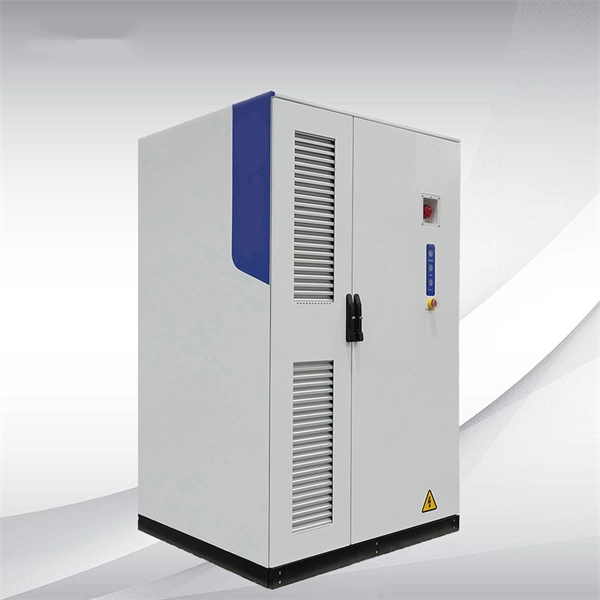
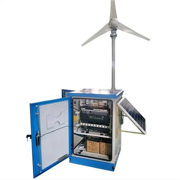
Outdoor Climate Cabinets
IP55/IP66 outdoor enclosures with integrated cooling/heating, -40°C to +55°C operation.
Smart PDUs & Power Distribution
Intelligent PDUs with remote monitoring, per-outlet switching, and environmental sensors.
Shelters & Network Cabinets
Prefabricated telecom shelters, emergency comms shelters, and network cabinets with cable management.