-
Low loss hollow fiber
Unlike traditional fibers that guide light through solid silica cores, HCF channels light through an air-filled central core, leveraging photonic bandgap or anti-resonant structures to minimize signal loss and dispersion. This study innovatively presents a hollow-core anti-resonant fiber integrating double-tube nesting and a single-layer anti-resonant wall. Featuring an exclusive two-layer cladding configuration along with an outer cladding circular ring, it differs significantly from traditional fibers. In practice HCF is built as a microstructured glass “jacket” surrounding a central air channel. Light is guided not by total internal reflection in glass but by photonic-bandgap or. In the ever-evolving landscape of fiber optic technology, hollow core fiber (HCF) emerges as a groundbreaking innovation, challenging the decades-long dominance of solid-core fibers. Additionally, the variations in the wall thickness.
[PDF Version]
-
The Role of Fiber Core in Optical Cable Splicing
At its core, fiber optic splicing involves joining two pieces of fiber optic cable to ensure that light pulses travel without disruption. This is achieved through fusion splicing or mechanical splices, each offering distinct advantages depending on the project requirements. The goal is to align the microscopic glass cores (typically. In this guide, you will find a chronological description of the fusion splicing process, the principal technical standards, and answers to the real-life questions network engineers and procurement teams may have. Professionals in telecommunications, data centers, and network infrastructure must understand the core functions and why they are fundamental to their fiber optic. The cladding is usually 125 microns in diameter and is uniform across most fiber types. Typically it is stripped away during preparation for fusion splicing. Ensure Your Splicing Tools are Clean – #2.
[PDF Version]
-
Sudan Warranty Hollow Core Fiber G 654
The fiber complies with or exceeds ITU-T Recommendation G. Standard 60793-2-50, type B1. 2, which has the zero-dispersion wavelength around 1300 nm wavelength, shows a cut-off shift at a wavelength around 1500 nm, is loss-minimized and is optimized for use in. Ultra-low loss (ULL) optical fibers, PureAdvance™ series compliant with G. E, support high-capacity long-haul terrestrial networks. Employing pure silica core technologies, we promise to contribute to low attenuation optical cable deployment. E, allow for the provision of an additional network margin that can be leveraged to enable reliable, high-data-rate transmissions over longer spans and extended reach. Coherent optical technology and G. Sumitomo Electric. HENGTONG designs and manufactures fiber preform offering superior performance and reliability. 200mm, corresponding to fiber over 15000km.
[PDF Version]
-
Remaining fiber cores in optical cable
First, clearly understand the number of wiring points and calculate the number of switches. Whether the connections between switches are stacked is also one of the considerations. Stacking: If the core switch i.
[PDF Version]
-
How to make an optical fiber splice
Learn how to splice fiber optic cable using fusion splicing with this complete step-by-step guide. Includes tools, best practices, loss standards (ITU-T G. 652), cost analysis, and FAQs for network engineers and installers. Ensure Your Splicing Tools are Clean – #2. Use and Maintain Your. Think of a fiber optic cable splice as the seamless stitching that keeps data flowing through the delicate threads of a network—like a master tailor joining fabric with precision.
[PDF Version]
-
How many cores of optical fiber cable does Indonesia use
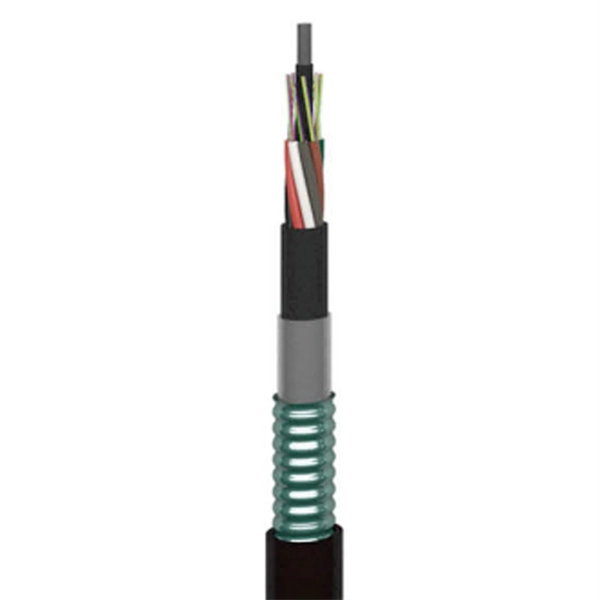
The deployed fiber-optic cable is based on Nexans' 24-core unrepeatered (URC-1) design. Near the shore, at water-depths below 20 meters, it will feature a double-armored (DA) construction for extra protection against damage from shipping and fishing activities. Telecommunication Statistics Indonesia presents data on the development of the telecommunications sector in Indonesia, which includes internet penetration rates, ownership of information and communication technology (ICT) facilities, usage patterns, as well as data on telecommunications networks. Indonesia - how many cores do I need for fiber optic cable internet connection, 1500 meters / 5000 feet How many cores do I need? I would run the cable myself above ground out of reach, using existing poles. This technician is trying to scam me with the cable (normal here). I am guessing I need. Indonesia Fiber Optics Market: Import Trend Analysis In the Indonesia fiber optics market, the import trend showed a growth rate of 0. The Palapa Ring project is also summarized, which aims to connect over 33 provinces and 460 districts across the. NEC Corp. For depths between 20 and 200 meters.
[PDF Version]
-
Does the polyethylene sheath of optical fiber cable contain formaldehyde
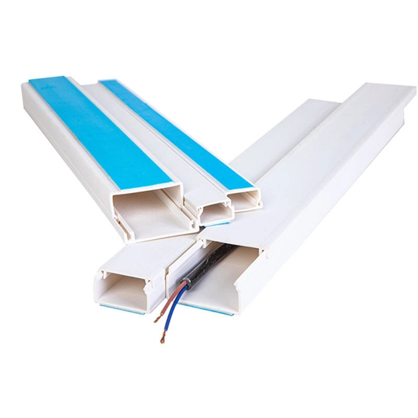
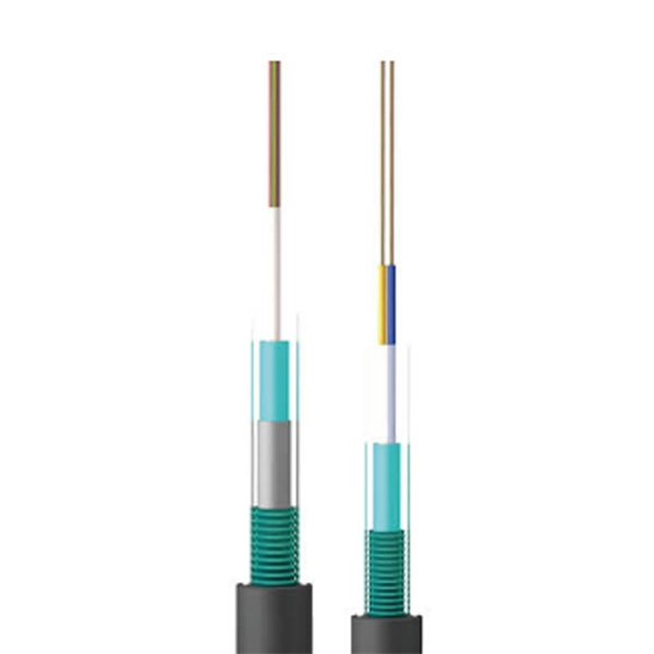
Generally speaking, the outer jacket of fiber optic cables is made of low smoke and halogen free materials (LSZH), cross-linked polyethylene (XLPE), and so on. Its primary functions include: While the optical fiber itself remains largely unchanged, the sheath material determines how the cable behaves in fire scenarios, outdoor environments, and long-term service conditions. The LSZH sheathed fiber optic cable can. Based on the density of the PE fiber cable outer sheath, there are also MDPE (middle density) and HDPE (high density). One of the primary advantages of PVC is its notable flexibility, which facilitates easy handling and installation, making it suitable for a broad range of. PE (Polyethylene) is a thermoplastic synthesized from the polymerization of ethylene (C2H4) under suitable pressure and temperature, widely used in the wire and cable industry. Disadvantages: Higher cost than PVC, generates a lot of black smoke when burning.
[PDF Version]
-
Sequential splicing of optical fiber cores
This is accomplished with a machine called a fusion splicer that performs two basic functions: aligning of the fibers and melting them together, typically using an electric arc. ”This is where fiber optic cable splicing—the process of creating a permanent, high-performance join between two fiber ends—becomes critical. For network managers and technicians, a poor splice can lead to significant signal degradation, network downtime, and costly troubleshooting. Regardless of the type of fiber network you're deploying, be it for telecom, enterprise data centers, or smart city infrastructure, fusion splicing provides the benefits of. This application note provides basic understanding and process of mass fusion splicing of optical fiber ribbons. As explained in industry resources, this technique achieves insertion losses as low as 0. 01 dB and minimizes back reflection—critical for maintaining.
[PDF Version]
-
How much optical attenuation does a single-mode fiber coupler experience
Attenuation quantifies in decibels per kilometer, with single-mode fibers exhibiting minimal 0. 15dB/km reductions at 1550nm. Additional losses arise from bending, impurities, and splices, compounding intrinsic effects. Fiber loss, also called fiber optic attenuation or attenuation loss, refers to the loss of signal between input and output. This transfer involves channeling the light, which carries data, from a source such as a laser or LED directly into the hair-thin. When dealing with single mode fiber (SMF) in optical communication systems, understanding and managing the acceptable dB (decibel) loss is crucial for maintaining efficient and reliable signal transmission. The acceptable dB loss for single mode fiber can vary depending on several factors. The attenuation coefficient of single-mode fiber is typically lower than that of multi-mode fiber due to its smaller core size and the fact that the light travels in a single straight line down the center of the fiber.
[PDF Version]
-
Color sorting of 192-core optical fiber cable
This guide explains the latest EIA/TIA-598-D fiber color-coding standard used to identify fiber types, inner fiber sequences, and connector polish styles. With clear tables and updated details, it serves as a comprehensive reference for technicians handling modern fiber optic. Understanding fiber‑optic color codes is essential for any technician tasked with installing, maintaining, or troubleshooting modern fiber networks. By adopting the TIA/EIA‑598C standard, you gain a universal “language” of colors that speeds identification, reduces miswiring, and enhances safety. This Applications Note addresses Corning Optical Communications' identification scheme for optical fiber cables. This identification scheme follows the TIA/EIA-598, “Optical Fiber Cable Color Coding. Hexatronic offers cables with color code systems according to all interna ional and national standards and for all types of fiber opti such as a tube, ribbon, yarn wrapped bundle or other types of bundle.
[PDF Version]
-
What dB value is considered acceptable for optical fiber splicing
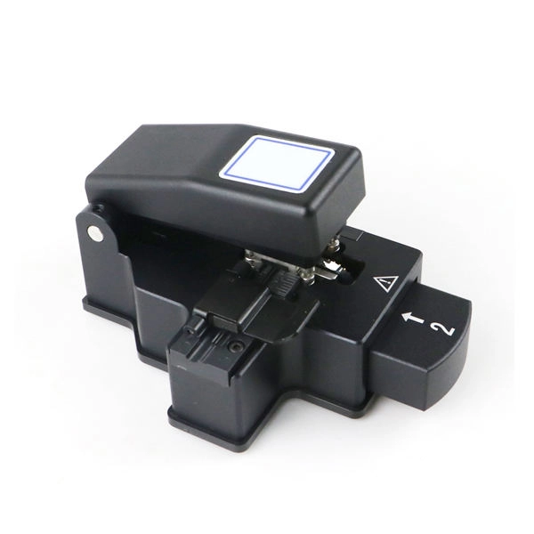
Acceptable splice loss in optical fiber is typically considered to be less than 0. What is the typical acceptable splice loss for single-mode fiber using fusion splicing? What is the acceptable splice loss for multimode fiber using mechanical splicing? How does fiber alignment affect splice loss? Why is cleaning the fiber important before splicing? What role does the cleaver play. Acceptable dB loss for fiber depends on the component you're measuring: a single mated connector pair should lose no more than 0. 5 dB per kilometer depending on the type and wavelength. The total. However, acceptable values depend on: * Project specifications * Link budget calculation * Network type (FTTH vs backbone) * Customer SLA requirements 🛠 Fusion vs Mechanical Splicing * **Fusion splicing** typically gives lower loss (0. * **Mechanical splicing** usually results in. The splice loss is measured in decibels (dB) and is influenced by various factors such as the quality of the splice, the alignment of the fiber cores, and the type of splicing technique used. 5 dB, while for multimode. For each connector, we usually figure 0. However, various factors, such as fibre cleanliness, core.
[PDF Version]
-
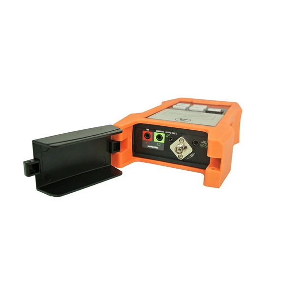
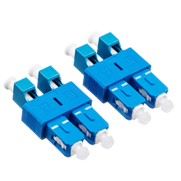
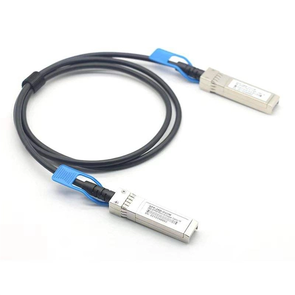
Will the light on the optical module illuminate when the fiber optic cable is plugged in
The LED status will not change when only the SFP module is plugged in. The LED will only light up when all connections are properly established and functioning correctly. When the connection does not work as expected after we set it up according to the Installation Guide, we need to do some troubleshooting. Should both Fiber SFP modules show a laser light in one of the two (duplex) receptacles? I followed this forums advice and ran some fiber in the conduit to a new detached garage. I had tested the fiber before running it to make sure it was working. The simplest way to test an SFP transceiver is with the FiberLert™ live fiber detector, which lights up and beeps when placed in front of an active fiber or port. ) does not receive a good signal from Switch A (Tx). The light from the end of the fiber is coupled to a receiver where a detector converts the light into an electrical signal which is then conditioned properly for use by. Looking at the SFP from the LC coupler, the left side is the light transmitter, the right side is the light receiver. An optic cable is composed of 2 joined optic fibers.
[PDF Version]
-

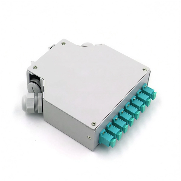
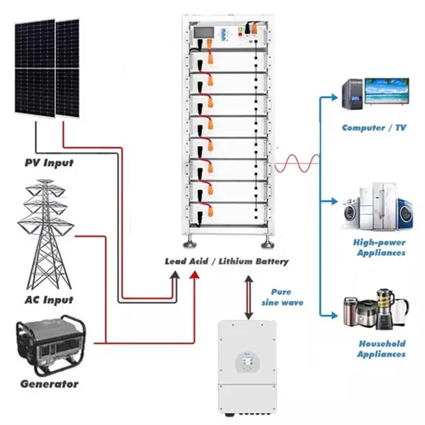
Will the optical fiber distribution box have a BBU
It sits in an enclosure with the Battery Backup Unit (BBU) and associated wiring. It has an optical port connecting to the external Customer Splice Point, an Ethernet port connecting to the communications provider's (CP) router, and a telephony port connecting to the voice. units on towers, buildings, or light posts. The RRU is normally located at the top of a tower, roof, or similar bu lding object and very close to the antenna. On the other end, the. RRU and BBU are crucial components in base station construction, enabling a distributed architecture that improves efficiency and reliability. In a distributed base station. Fiber Optic Distribution Box (FDB) / Fiber access terminal box (FAT) / optical termination box (OTB) / Fiber termination box (FTB) / Optical Distribution box (ODB) are a compact fiber management box used for FTTH application. For more. The enclosure is attached to the wall with 2 screws, instead of the 4 on the previous ONT A template is provided with the unit to ensure correct screw location The enclosure will fit over a double back box to allow the connectorised cable to be inserted through the back of the unit.
[PDF Version]
-
Cable and Optical Fiber Survey Report
The report on the fiber optic cable market provides a holistic analysis, market size and forecast, trends, growth drivers, and challenges, as well as vendor analysis covering around 25 vendors. Fiber optic cables are needed for backhaul and fronthaul connectivity because they provide the required bandwidth for 5G base stations and small cell networks. Public cable companies lost 265,000 Internet customers in Q3 2024. 0 will significantly stem this trend. Where Are We Going? to telecom in the past five years (the majority to fiber). Disbursement occurs over multiple years. 19 billion by 2033, expanding at a CAGR of 10. Cable operators plan to carry out a growing number of network upgrades and new builds over the next 5 years, including FTTP-oriented, DAA-oriented, PON-oriented, DOCSIS-oriented, and. The UTC Fiber subcommittee serves as a platform for utility industry professionals and executives to address present and future challenges related to fiber optic networks. I need the full data tables, segment breakdown, and.
[PDF Version]
-
Brief Answer on Optical Fiber Communication Optical Receivers
Fiber optic receivers convert light signals into electrical signals for use by equipment such as computer networks. These electro-optical devices consist of an optical detector, a low-noise amplifier, and signal conditioning circuitry. The primary function of an optical receiver in an optical fiber communication link is to convert the received. Most systems operate by transmitting in one direction on one fiber and in the reverse direction on another fiber for full duplex operation. Most systems use a "transceiver" which includes both transmission and receiver in a single module.
[PDF Version]
Telecom Racks & Cabinets
19-inch racks, wall-mount cabinets, open frames with high load capacity and seismic rating.
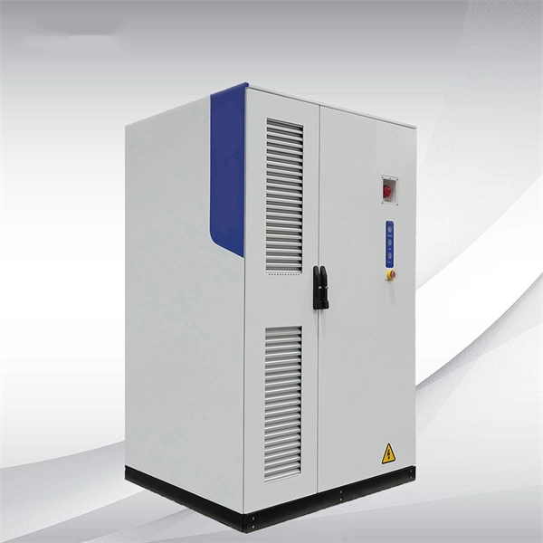
Outdoor Climate Cabinets
IP55/IP66 outdoor enclosures with integrated cooling/heating, -40°C to +55°C operation.
Smart PDUs & Power Distribution
Intelligent PDUs with remote monitoring, per-outlet switching, and environmental sensors.
Shelters & Network Cabinets
Prefabricated telecom shelters, emergency comms shelters, and network cabinets with cable management.