-
How to select the number of optical fiber cores
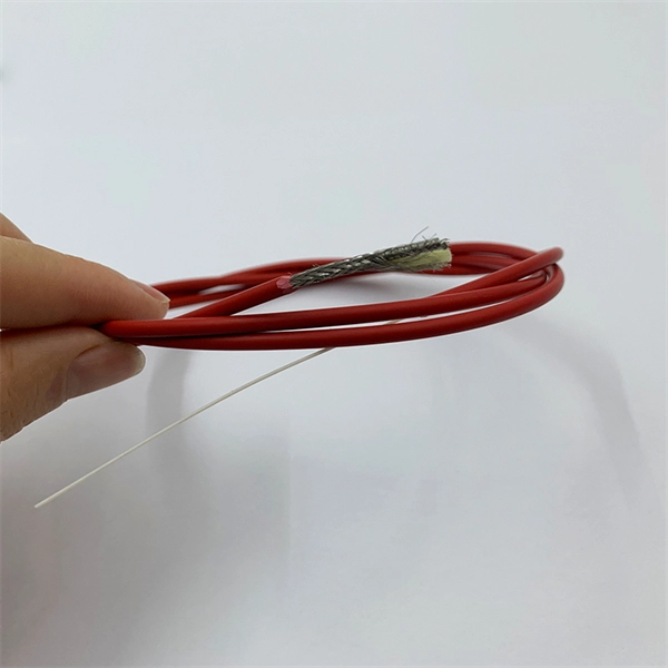
The number of optical cores in an optical fiber is the total number of equipment interfaces multiplied by 2, plus 10% to 20% of the spare quantity, and if the communication mode of the equipment has serial communication and equipment multiplexing, you can reduce the number of cores. This article will walk you through the basics of fiber optic cores and provide practical guidance for selecting the suitable fiber optic cable to meet your networking needs. Made from either high-quality. Fiber optic cables consist of multiple thin strands of glass or plastic, known as “cores. ” These cores carry the data signals via light. The number of. Common fiber cores include 1 core, 2 cores, 6 cores, 8 cores, etc.
[PDF Version]
-
How to select the number of optical cores in a fiber optic cable
The number of optical cores in an optical fiber is the total number of equipment interfaces multiplied by 2, plus 10% to 20% of the spare quantity, and if the communication mode of the equipment has serial communication and equipment multiplexing, you can reduce the number of cores. Fiber cores are the heart of fiber optic cables, transmitting light signals that carry data. Made from either high-quality glass or plastic, the core plays a critical role in determining the cable's performance.
[PDF Version]
-
How many cores are ideal for a telecommunications fiber optic cable
Multi-core fiber optic cables can contain 3 to 12 cores within a single cable. This significantly increases the data transmission rate, making them ideal for modern, high-demand applications. Understanding Fiber Cores: Core: The central glass fiber that transmits light signals. The number of cores you choose directly impacts the capacity and. The number of optical cores in an optical fiber is the total number of equipment interfaces multiplied by 2, plus 10% to 20% of the spare quantity, and if the communication mode of the equipment has serial communication and equipment multiplexing, you can reduce the number of cores. The number of. When planning outdoor fiber networks—whether for duct installations, aerial deployments, or direct burial—one critical question arises: How many cores does a GYTA cable offer? As a staple loose-tube armored fiber optic cable, GYTA is celebrated for its flexibility in core counts, tailored to. Fiber cores are the central components of fiber optic cables, responsible for transmitting light signals that carry data.
[PDF Version]
-
Number of fiber optic connector cores
Multimode fiber optic cables can have multiple cores, commonly 2 or 4. The number of cores refers to the individual strands within the cable that carry the optical signals. These cores allow for the transmission of multiple signals simultaneously, increasing the capacity and. The number of optical cores in an optical fiber is the total number of equipment interfaces multiplied by 2, plus 10% to 20% of the spare quantity, and if the communication mode of the equipment has serial communication and equipment multiplexing, you can reduce the number of cores. Made from either high-quality. At TARLUZ, we understand that selecting the right fiber core count is critical for network performance, scalability, and cost-effectiveness. They are typically made of high-quality glass.
[PDF Version]
-
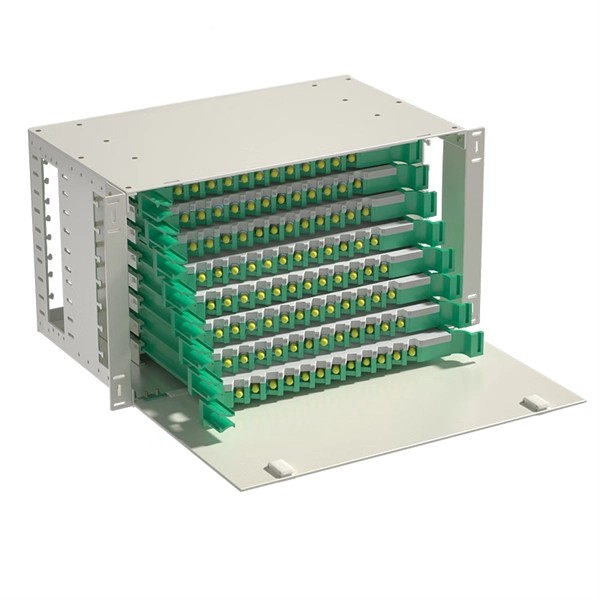
How to configure the number of ports on a fiber optic patch panel
Here's a step-by-step guide to help you properly arrange fiber optic patch panels in a data center environment. Before installation, assess your network's current and future needs: Use this information to select the appropriate patch panel type—rack-mounted, wall-mounted, or modular high-density. Fiber patch panels come in various configurations, including 12-port, 24-port, 48-port, 72-port, 96-port, and 144-port fiber distribution frames. These options cater to different network requirements and capacities. The most common configurations are 24 port fiber patch panel and 48 port fiber. ● The patch panel is a long-term solution that can provide high-density port connectivity solutions for 4x10 Gbps, 100 Gbps, 2x100 Gbps, 4x100 Gbps, 400 Gbps, 2x400 Gbps, and 4x400 Gbps breakout requirements. And label the ports to identify different cables so that technicians have clear instructions on what they need. Suitable to SC LC FC ST or other fiber connectors as requested, Meanwhile, 12, 24, 36, 48, 72, 96, 144 ports are available Mounted directly onto walls for space-saving installations.
[PDF Version]
-
How to Choose a Fiber Optic Cable Identifier in Greece
Use color coding for fiber types to quickly identify cables. Yellow indicates single-mode fiber, while orange and aqua mark multimode fibers. Follow TIA-606-B standards for labeling. With clear tables and updated details, it serves as a comprehensive reference for technicians handling modern fiber optic installations. By adopting the TIA/EIA‑598C standard, you gain a universal “language” of colors that speeds identification, reduces miswiring, and enhances safety across cable jackets, connectors, buffer tubes, and splice trays. You rely on these color systems to ensure correct fiber routing, splicing accuracy, tube identification, polarity. Have you ever wondered how the installers can identify every single fiber in a cable with hundreds of fibers? Well, this would be impossible without a standardized system. Since fibers are tiny (about 250 µm in diameter), number marking, or other printed markings is not practical.
[PDF Version]
-
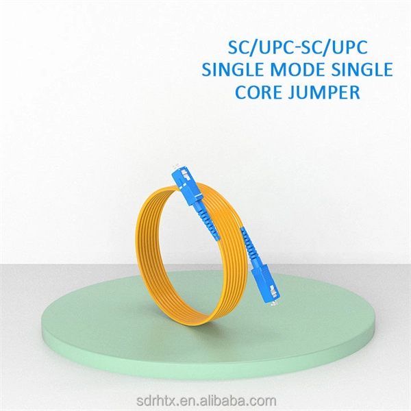
How many fiber optic cores can a single optical module connect to
A simple rule is that each device needs two cores—one for sending and one for receiving data. Start by counting how many devices you're connecting. (actually use a four core optical cable) This is because apart from one-core optical fiber, there are basically no optical cables with an odd number of cores, such as three-core, five-core, etc. It is worth. The total number of cores for a 1pc fiber patch cable is calculated as the number of branches multiplied by the number of cores per branch (if there are no branches, the number of branches = 1). In the context of accelerating digitalization, the rational. o In optical modules, "core" refers to the light-transmitting channel in the fiber.
[PDF Version]
-
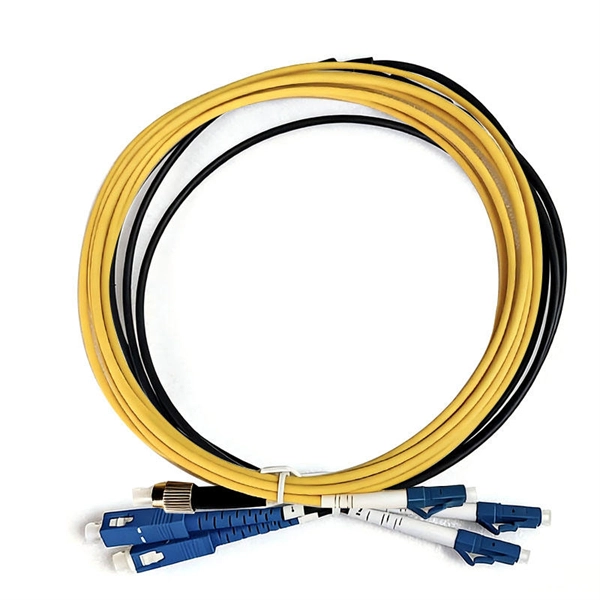
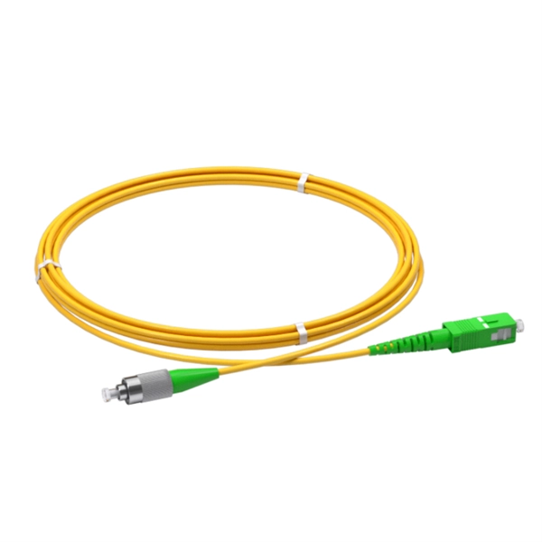
How many fiber optic cores does a fiber optic patch cord contain
Multi-core patch cords are fiber assemblies containing multiple fibers within a single cable jacket, typically available in 4, 6, 12, and 24-fiber configurations. These assemblies are widely used in ODN distribution frames, data center racks, MDU risers, and fiber management systems where higher. Fiber cores are the heart of fiber optic cables, transmitting light signals that carry data. Made from either high-quality glass or plastic, the core plays a critical role in determining the cable's performance. Fiber optic patch cords (also known as fiber optic connectors) are fiber optic cables fitted with connector plugs at both ends, which are used to achieve the optical path. Connecting fiber optic cables to patch panels may seem like a straightforward task, but improper connections can lead to signal loss, decreased network efficiency, and even costly repairs. That's why understanding the proper techniques and tools for this process is essential.
[PDF Version]
-
How many cores of optical fiber cable does Indonesia use
The deployed fiber-optic cable is based on Nexans' 24-core unrepeatered (URC-1) design. Near the shore, at water-depths below 20 meters, it will feature a double-armored (DA) construction for extra protection against damage from shipping and fishing activities. Telecommunication Statistics Indonesia presents data on the development of the telecommunications sector in Indonesia, which includes internet penetration rates, ownership of information and communication technology (ICT) facilities, usage patterns, as well as data on telecommunications networks. Indonesia - how many cores do I need for fiber optic cable internet connection, 1500 meters / 5000 feet How many cores do I need? I would run the cable myself above ground out of reach, using existing poles. This technician is trying to scam me with the cable (normal here). I am guessing I need. Indonesia Fiber Optics Market: Import Trend Analysis In the Indonesia fiber optics market, the import trend showed a growth rate of 0. The Palapa Ring project is also summarized, which aims to connect over 33 provinces and 460 districts across the. NEC Corp. For depths between 20 and 200 meters.
[PDF Version]
-

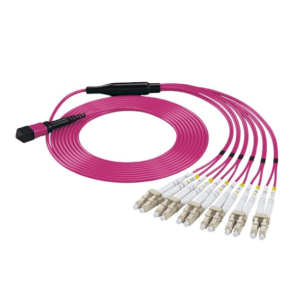
How many fiber cores should a fiber optic splitter connect to
A simple rule is that each device needs two cores—one for sending and one for receiving data. This guide focuses on two critical aspects of optical splitters that define FTTH performance: split ratios (how signals are divided) and splitting architectures (how splitters are deployed). By understanding these elements, network operators can design PON (Passive Optical Network) systems that. The total number of cores for a 1pc fiber patch cable is calculated as the number of branches multiplied by the number of cores per branch (if there are no branches, the number of branches = 1). For example, the total number of cores in an MTP®-8 trunk cable equals 4 (number of branches) x 8 (MTP-8. The number of optical cores in an optical fiber is the total number of equipment interfaces multiplied by 2, plus 10% to 20% of the spare quantity, and if the communication mode of the equipment has serial communication and equipment multiplexing, you can reduce the number of cores. As XGS-PON continues to be adopted, some service.
[PDF Version]
-
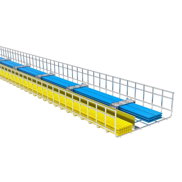
How to separate the fiber cores of OPGW24-core optical cable
Removing the aluminum strands and outer layers of the OPGW cable exposes the fiber optic cores 7, which is essential for proper termination. Use a file to smooth any sharp edges after removing the aluminum strands 8. Carefully separate the metal loose tubes without damaging. Proper termination of OPGW cables involves precise steps like careful handling 3, removing outer layers, cleaning fibers, and securing with clamps. In the construction of electric power dedicated communication network, the number of optical fibers used is usually 12 to 24 cores. With the continuous expansion of system capacity according to new business requirements, the number of cores is gradually increasing, and individual line sections have. out this step, cut a small piece of pipe, about 2 feet, from the free end of the cable and practice cuttin of the cable. While holding the cable, pull the optical units completely out of the pipe by pullin toward the tower. What is Fiber Optic Splicing and Why is it Needed? – #1. First, a heat-shrink tube is placed over the OPGW cable.
[PDF Version]
-
How to calculate the number of ports on a fiber optic patch panel
The fundamental calculation formula is: Total patch cords = Total number of device ports × Connection factor Where the connection factor depends on the connection method: 2. Scenario-Based Calculations The redundancy factor is typically 0 (no redundancy) or 1 (1:1 redundancy). Premium-Line 19” Rack mountable fiber optic patch panel is designed for both patching and splicing, accepts whole range of adapters including SC, ST, FC, LC adapters. 2 * Rear cable entries accommodate cables with diameter below 10mm. These options cater to different network requirements and capacities. Network architects and procurement managers must now evaluate patch panels not merely. Follow TIA-942 or ISO/IEC 11801 standards for structured cabling. It is important to know the.
[PDF Version]
-
How to Choose an Italian Fiber Optic Sensor
Use this fiber-optic sensors buying guide to compare major types, define selection criteria, and find suppliers: Professional purchasing of high-value photonics products is a substantial responsibility, where a structured decision-making process is essential. RP Photonics. Fiber optic sensors are pivotal components in modern sensing technology, underpinning high-precision detection across critical industries from industrial manufacturing to infrastructure monitoring. OST is able to propose the most suitable technology for all measurement requirements, developing custom solutions for every. When installation space is extremely limited or the objects to be detected are tiny, fiber-optic sensors are the ideal solution. Detection in Narrow Locations The small sensing section and flexible Fiber Unit cable enable a Fiber Sensor to. Our global manufacturing network for fiber optic sensors in Ayabe (Japan), Shanghai (China) and Nufringen (Germany) focuses on continuously optimising methods for small and large volume production, applying stringent quality control procedures, and expanding production portfolio and flexibility to.
[PDF Version]
-
How far should the power fiber optic cable be from the house
For indoor fiber optic cables, the maximum pulling distance typically ranges from 100 to 200 meters. The shorter distance accounts for the lower tensile strength and the need for gentle handling to avoid damage to the delicate fibers. This composite cable combines the distance and bandwidth capabilities of singlemode fiber with the power-carrying capability of 14-AWG copper conductors. by Jeanna Deese and Chris Rivas Power over Ethernet—it may be an old concept, but new applications continue to be identified that are redefining. Unlike Power over Ethernet (PoE), which is limited by copper cable characteristics, PoF leverages optical fiber to overcome distance, electromagnetic interference, and safety constraints. It depends on multiple. Need some clarification about NEC 770. Is this 300 mm separation from the center of the power cable to the center of the fiber optic cable, or is it from the side of the power. The pulling distance of fiber optic cables depends on several factors, including the type of cable, installation environment, and pulling techniques. Understanding these factors is crucial for planning and executing a successful installation.
[PDF Version]
-
How to set up a 20Mbps China Unicom fiber optic router
To set up your router for fiber internet quickly, connect the router to your fiber modem, access the router's settings via a web browser, and input the provided ISP credentials. If you've purchased this device and don't know where to start, don't worry. Follow these steps and you'll be able to enjoy a stable and. However, setting up a fiber optic connection to your router can seem daunting if you're unfamiliar with the process. The exact composition of this. How to solve after the light cat is reset? 1. Our Experts are helping user's, who are facing issues with their tech gadgets like Router, Modem and extender.
[PDF Version]
Telecom Racks & Cabinets
19-inch racks, wall-mount cabinets, open frames with high load capacity and seismic rating.
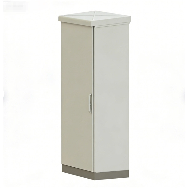
Outdoor Climate Cabinets
IP55/IP66 outdoor enclosures with integrated cooling/heating, -40°C to +55°C operation.
Smart PDUs & Power Distribution
Intelligent PDUs with remote monitoring, per-outlet switching, and environmental sensors.
Shelters & Network Cabinets
Prefabricated telecom shelters, emergency comms shelters, and network cabinets with cable management.