-
In optical fiber cable engineering the OLT is
An Optical Line Terminal (OLT) serves as the main aggregation and connection point in fiber optic communication networks. It provides two main functions: to perform conversion between the electrical signals used by the service provider's equipment and the. In the age of fiber-to-the-home (FTTH) and ultra-broadband connectivity, the Optical Line Terminal - or OLT - is one of the most crucial devices powering our high-speed digital world. When you stream a 4K video, join a remote meeting, or play an online game on a gigabit fiber connection, an OLT. A GEPON system usually consists of an OLT (Optical Line Terminal) at the service provider's central office and multiple ONU (Optical Network Units) or ONT (Optical Network Terminals) close to the end user as optical splitters. It can transmit and receive data at several hundreds of kilometers without loss. It functions like a router or switch in a traditional network but tailored for fiber optics.
[PDF Version]
-
Sequential splicing of optical fiber cores
This is accomplished with a machine called a fusion splicer that performs two basic functions: aligning of the fibers and melting them together, typically using an electric arc. ”This is where fiber optic cable splicing—the process of creating a permanent, high-performance join between two fiber ends—becomes critical. For network managers and technicians, a poor splice can lead to significant signal degradation, network downtime, and costly troubleshooting. Regardless of the type of fiber network you're deploying, be it for telecom, enterprise data centers, or smart city infrastructure, fusion splicing provides the benefits of. This application note provides basic understanding and process of mass fusion splicing of optical fiber ribbons. As explained in industry resources, this technique achieves insertion losses as low as 0. 01 dB and minimizes back reflection—critical for maintaining.
[PDF Version]
-
How much optical attenuation does a single-mode fiber coupler experience
Attenuation quantifies in decibels per kilometer, with single-mode fibers exhibiting minimal 0. 15dB/km reductions at 1550nm. Additional losses arise from bending, impurities, and splices, compounding intrinsic effects. Fiber loss, also called fiber optic attenuation or attenuation loss, refers to the loss of signal between input and output. This transfer involves channeling the light, which carries data, from a source such as a laser or LED directly into the hair-thin. When dealing with single mode fiber (SMF) in optical communication systems, understanding and managing the acceptable dB (decibel) loss is crucial for maintaining efficient and reliable signal transmission. The acceptable dB loss for single mode fiber can vary depending on several factors. The attenuation coefficient of single-mode fiber is typically lower than that of multi-mode fiber due to its smaller core size and the fact that the light travels in a single straight line down the center of the fiber.
[PDF Version]
-
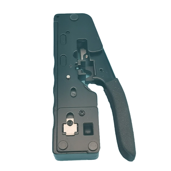
How to quickly splice 12-core optical fiber
Learn how to splice fiber optic cable using fusion splicing with this complete step-by-step guide. Includes tools, best practices, loss standards (ITU-T G. 652), cost analysis, and FAQs for network engineers and installers. Regardless of the type of fiber network you're deploying, be it for telecom, enterprise data centers, or smart city infrastructure, fusion splicing provides the benefits of. Fiber optics is the fastest and one of the safest ways to transmit information online. Fiber optic strands are ultra-lightweight and about as thin as human hair, and yet, they have more than eight times the pulling tension of a copper wire. Discover how to efficiently use sleeves and the heat. Field-terminating connectors is a meticulous, high-pressure process where even a tiny mistake can force you to cut the fiber and start all over again. This is exactly why most professional installers have moved away from field-termination and toward splicing.
[PDF Version]
-
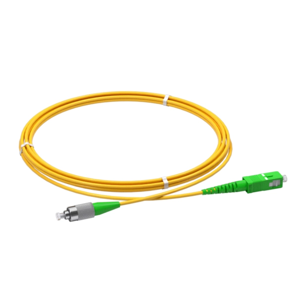
Belarusian large-core optical fiber 1310nm
In this article, we explore the key characteristics, common applications, and important comparisons related to 1310nm optical modules. Used for medium-distance links in city networks. As part of the O-band (1260–1360 nm), it balances low dispersion, stable performance, and cost efficiency. This makes it widely adopted in data centers, enterprise backbones, and metro access. The product features an SFP+ package with an LC connector, a 1310nm DFB laser with a PIN photodetector, and supports up to 20km transmission on SMF with power dissipation under 1W. Or It is also suited for analog fiber transmission. Pricing (USD) Filter the results in the table by unit price based on your quantity. A. 10GBASE-LRM SFP+ Transceiver Module 1310nm 220m - FS. com FS United StatesFREE SHIPPING on Orders Over US$79 Contact Us United States / $ USD Sign in Sign up Search Recent Searches Change FREE SHIPPING on Orders Over US$79 United States HomeOptical Transceivers10/25/40/100G. SFP+, 1310nm, LR SMF 10km, 10G DDM, Corning 1LAN-SFPP-10GB-LR Compatible Integra manufactures the highest quality SFPP transceivers in the industry, designed to be 100% interoperable with all OEM platforms.
[PDF Version]
-
How to separate the fiber cores of OPGW24-core optical cable
Removing the aluminum strands and outer layers of the OPGW cable exposes the fiber optic cores 7, which is essential for proper termination. Use a file to smooth any sharp edges after removing the aluminum strands 8. Carefully separate the metal loose tubes without damaging. Proper termination of OPGW cables involves precise steps like careful handling 3, removing outer layers, cleaning fibers, and securing with clamps. In the construction of electric power dedicated communication network, the number of optical fibers used is usually 12 to 24 cores. With the continuous expansion of system capacity according to new business requirements, the number of cores is gradually increasing, and individual line sections have. out this step, cut a small piece of pipe, about 2 feet, from the free end of the cable and practice cuttin of the cable. While holding the cable, pull the optical units completely out of the pipe by pullin toward the tower. What is Fiber Optic Splicing and Why is it Needed? – #1. First, a heat-shrink tube is placed over the OPGW cable.
[PDF Version]
-
Fiber optic fault breakpoint in optical time domain reflectometer
These reflections indicate splices, bends, breaks, and other faults. The OTDR trace provides a visual representation of these events, allowing technicians to pinpoint and address issues. The launch pulse appears as a large initial spike on the OTDR trace. Enter the Optical Time-Domain Reflectometer (OTDR) —a powerful tool for diagnosing, testing, and maintaining fiber optic cables. This guide dives deep into OTDR technology, its applications, and how it integrates with modern components like optical transceivers. We improve the level of equipment, but also by implementing fine operations can. OTDR testing analyzes fiber optic cable performance from end to end by testing components along the cable, including connection points, bends, and splices. Proper interpretation of OTDR trace results is crucial for efficient troubleshooting. Configure your OTDR correctly by setting the right.
[PDF Version]
-
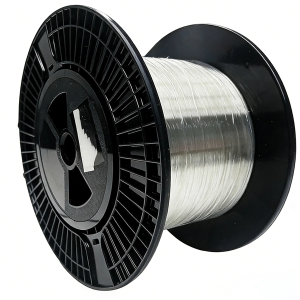
How to make a communication optical fiber cable
In this factory tour, you'll see the step-by-step process of how glass fibers are turned into high-quality optical fiber cables. The precision and care behind each cable ensure fast and reliable data transmission. Fiber optic cables have revolutionized the way we communicate and access information in the modern world. The process to learn How to Make a Fiber Optic Cable? requires specialized equipment and expertise, starting with creating a preform and. The manufacturing process of fiber optic cables is a fascinating journey involving cutting-edge technology, precision engineering, and strict quality control. In this blog, we'll take a closer look at the step-by-step fiber optic cable manufacturing process, the materials used, and why these cables. Full Process of Optical Fiber Cables Making Have you ever wondered how optical fiber cables are made? In this video, we take you inside the factory to show the full process of optical fiber cable manufacturing. This article covers these steps.
[PDF Version]
-
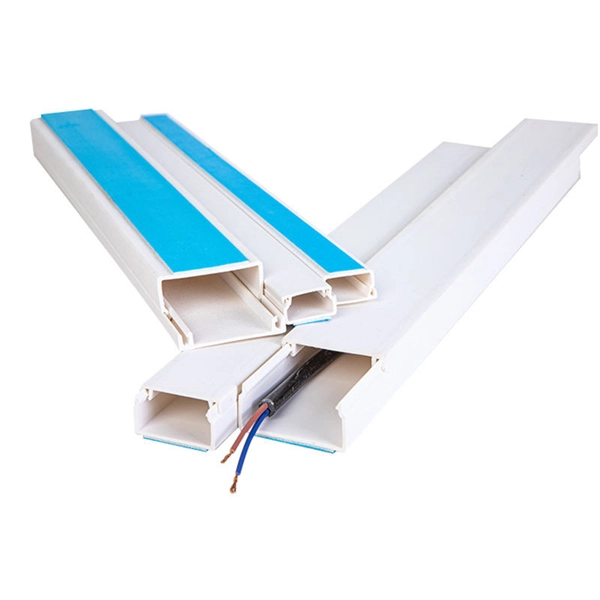
Wired transmission media include optical fiber
Wired media: The physical connection between two communication devices that carries the signal from one side to the other. Common wired media include twisted pair, coaxial cable, and optical fiber. Wired communication offers reliability and stability, but requires cabling and can be inconvenient for mobile devices. With guided media, the waves are guided along a solid medium. Wireless transmission media, as the name suggests, refers to the technology used to transmit information from one device to another without the use of a physical connection.
[PDF Version]
-
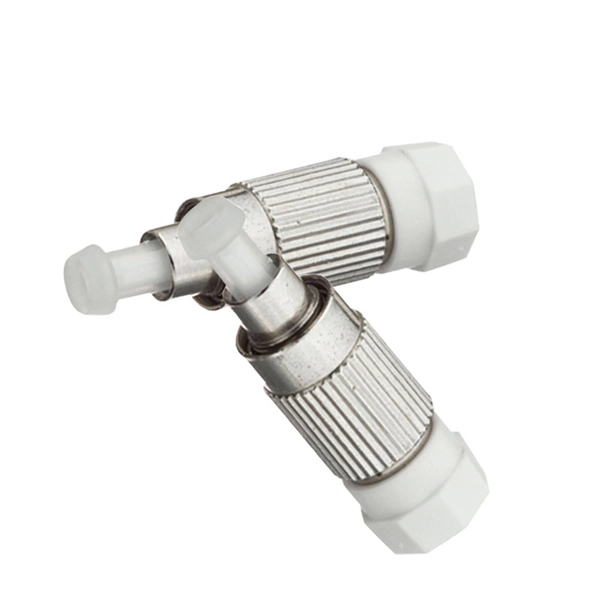
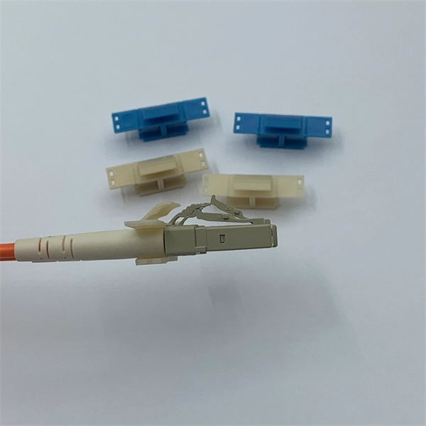
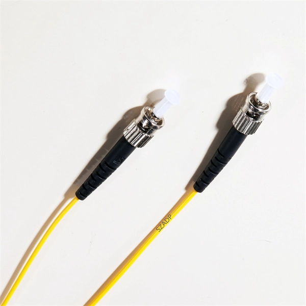
What does CSC in optical fiber represent
The CS Consortium represents technology leaders committed to providing the most current, reliable, and vendor neutral information about fiber optics and related technologies for advancing new and better communications solutions. What is a CS optical Connector Fiber Optic Cable? Comparison with LC and SN Connectors Home / Resources / Blog & News / What is a CS Connector Fiber Optic Cable? What is a CS Connector Fiber Optic Cable? Explore the benefits of CS optical connector fiber optic cables for 200G, 400G, and 800G. The CS Consortium is a group of leading fiber optic component manufacturers that focuses on educating end users and design consultants about the technical advantages of using CS based high density connectivity solutions. The connector mechanically aligns the fiber cores, enabling light to pass and. Optical Fiber (OFC): Thin strands of glass/plastic that guide light. Mode: A single path for light to travel within the fiber. Used for long-distance, high-speed.
[PDF Version]
-
How to weld aluminum strips in optical fiber cables
There are several methods to achieve this. The most popular ones include: mechanical welding - with the use of mechanical joints and thermal welding with the use of a welding machine, and the third option, i. the technique of polishing joints and gluing. Optical cable transverse stripping knife, vise, utility knife, scissors, strengthening core cutters, toilet paper and alcohol cotton balls Methods and procedures of optical cable stripping 1, according to the actual determine the cable stripping length, generally in 1. 2, with optical cable. Whether you're a beginner or an experienced welder, this page has all the information you need to successfully weld aluminum using the MIG process. From detailed settings charts that guide you through the intricate world of voltage, amperage, and wire feed speed, to a breakdown of the best aluminum. Fiber Optic Welding How To Joint Fiber Optic Cablesplicing fiber optic cable,fiber optic splice,fiber optic,fiber optics,fiber splice,how to splice,fibre opt. Reheated to. As a premium filler metal solution, Hobart aluminum wire is supported and manufactured by a team with decades of expertise in aluminum filler metals.
[PDF Version]
-
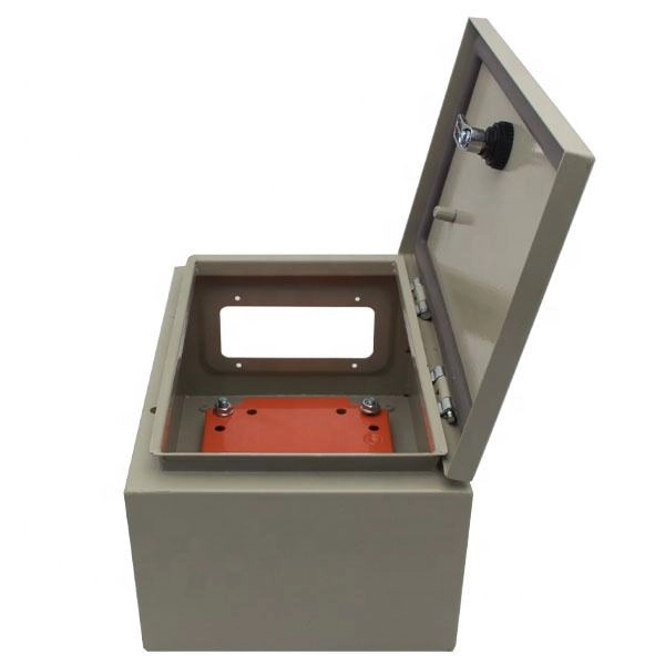
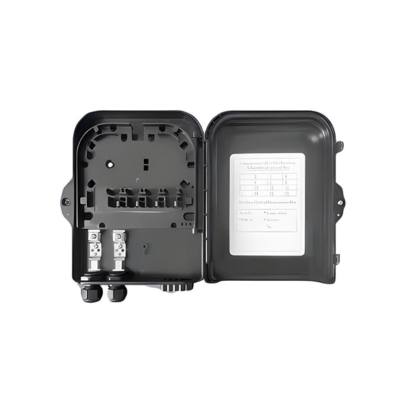
How many ports does the optical fiber splitter distributor have
Featuring 24 fiber ports, comprising 3 inlet, 16 outlets, this fiber optic splitter box ensures seamless connectivity across your fiber optic infrastructure. Cost Efficiency: A single OLT port can serve 8–64 ONTs via a splitter, reducing the number of OLTs, fibers, and deployment labor needed. Passive Operation: Splitters have no active electronics, so they require no power, cooling, or maintenance—lowering operational costs (OPEX) for ISPs. Indoor/Outdoor Wall Mounted, Single Door Fiber Distribution box is ideal for end terminations of fiber optic runs in residential or commercial buildings. Integral gasket seal provides IP65 level of protection. Pre-installed with 24 SC/APC simplex couplers and two 1x8 terminated SC/APC splitters, it effortlessly supports single-mode fiber optic. A fiber broadband provider typically determines and overall split ratio for the network, such as 1x32 or 1x64, and uses combinations of splitters to meet that ratio with each PON port. 1x32 splits were common in North America for G-PON architectures.
[PDF Version]
-
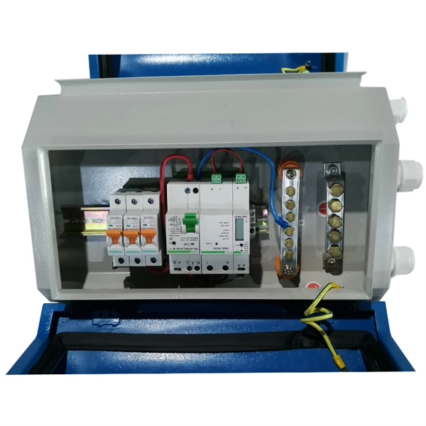
What are the benefits of lightning protection for optical fiber lines
Implementing lightning protection strategies such as surge protection devices, grounding systems, lightning rods, and proper cable design can help safeguard fiber optic cables and the networks they support. Lightning-induced surges can travel through power lines, telecommunication lines, or nearby metallic structures and pose a. Lightning protection is one of the key reasons for utilizing fiber optics. Unlike copper wire, the fiber itself is made from dielectric (non conducting) materials, cannot conduct electrical current, and is immune to EM radiation. Telecommunication equipment and communication lines located at or. Although the signals in fiber cables are optical signals, most of the outdoor optical cables using reinforced cores or armored optical cables are easy to get damaged under lightning because of the metal protective layer inside the cable. Since the lightning. It is well known that optical fiber has no electrical conductivity and can prevent from impact current.
[PDF Version]
-
Source manufacturer of optical fiber cables for communication in Democratic Republic of Congo
Genew Technologies and Zhongshi Wosen, both Chinese companies, will help the Democratic Republic of Congo (DRC) build its fiber optic network. Our vision is to become the leading solution provider in Fiber Optic communication system by providing Leading Brands and 'state of the art' services. Its main product is the internet for professionals. Having therefore. The Democratic Republic of Congo (DRC) is poised for a significant boost in its digital infrastructure following the signing of a Memorandum of Understanding (MoU) between the Congolese Optical Fiber Company (SOCOF) and the Agency for Steering, Coordination and Monitoring of Collaboration. SOCOF is a one-person limited company in which the Congolese State is the sole shareholder. It is governed by the Uniform Act revised on January 30, 2014 relating to the law of Commercial Companies and Economic Interest Grouping and by all other laws and regulations in force in the DRC, not.
[PDF Version]
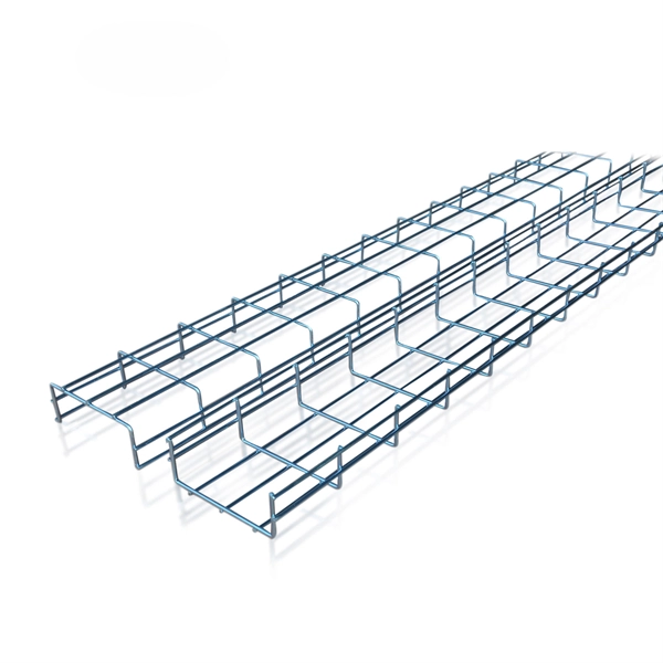
Telecom Racks & Cabinets
19-inch racks, wall-mount cabinets, open frames with high load capacity and seismic rating.
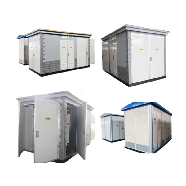
Outdoor Climate Cabinets
IP55/IP66 outdoor enclosures with integrated cooling/heating, -40°C to +55°C operation.
Smart PDUs & Power Distribution
Intelligent PDUs with remote monitoring, per-outlet switching, and environmental sensors.
Shelters & Network Cabinets
Prefabricated telecom shelters, emergency comms shelters, and network cabinets with cable management.