-

What does STJ mean in relay protection
Microprocessor-based solid-state digital protection relays now emulate the original devices, as well as providing types of protection and supervision impractical with electromechanical relays. Electromechanical relays provide only rudimentary indication of the location and origin of a. Designers uses short name (abbreviation) for the electrical components and equipment in electrical drawings that describes about components or equipment to electrician. Use Ctrl + F on your computer to search the electrical full forms you are looking for. DC – Direct. The protection and control devices in electrical equipment can be referred to by numbers, with appropriate suffix letters when necessary, according to the functions they perform. When the actuating quantity, such as the current or. The relays are in round glass cases. Letters are sometimes added to specify the application (IEEE Standard C37.
[PDF Version]
-
The Development History of Relay Protection Abroad
The world of power system protection has witnessed remarkable technological advancements over the past century. One of the most significant developments has been the evolution of protective relays—devices that are crucial for detecting faults and initiating protective actions. In 1901, the induction-type overcurrent relay was introduced, followed by ASEA (now ABB) launching the first time-delay overcurrent relay, TCB, in 1905, enabling graded protection. The current differential protection principle. Relay protection is a critical component of electrical power networks, providing rapid and reliable fault detection, isolation, and fault clearing to ensure system stability and equipment protection. It has a long and fascinating history that reflects the evolution of power systems and the. The exact date of the birth of the first fuses is still in question. Dolivo-Dobrovolsky can rightly be considered the founding father of relay protection.
[PDF Version]
-

The role of relay protection in distribution networks
Effective relay protection schemes safeguard the distribution network from faults and anomalies, ensuring minimal disruption and damage. As we integrate more renewable energy sources and advanced technologies, the task of ensuring reliable and efficient power. Line protection plays a vital role in ensuring the reliability and safety of distribution networks. In distribution systems, line protection is focused on detecting and isolating faults occurring on the network lines, thus preventing any potential damage to the system and minimizing downtime.
[PDF Version]
-
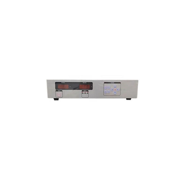
Relay Protection Debugging Platform QC
The equipment can simulate the current and voltage during power system faults, and can be used for the operation, maintenance, debugging, and calibration of power system relay protection devices. It has 4 channels of voltage and 3 channels of current output, with an output. RTSoft Relay protection monitoring, diagnostics and operation assessment system is a comprehensive solution for automating the workflow of protection engineers who service relay protection devices (IEDs) in power utilities, oil & gas and industrial enterprises. Download our detailed product. Bo Li, Xingyi Power Supply Bureau, Guizhou Power Grid Limited Liability Company, Xingyi 562400, China. Ensuring the operational reliability of substation relay protection systems through rapid defect diagnosis and state assessment is crucial for maintaining power system stability. Tailored for use in power plants, substations, and electrical grids, this advanced.
[PDF Version]
-
How often should relay protection be used
In a typical application, Protective Relay Testing should be conducted at least every two years in accordance with NFPA 70B. This utility standard establishes the requirements for testing and maintaining protection systems, automatic reclosing, and sudden pressure relaying. When a relay malfunctions or fails, the costs can be severe: equipment damage, safety threats, and even prolonged power outages. In HV (High Voltage) and MV (Medium Voltage) substations, relay protection safeguards critical assets such as transformers, circuit breakers, and lines. Many important issues, such as coordination of settings, operating times, characteristics of. Incorrect operation of motor protective relays could remove essential motors from service, resulting in economic loss due to process interruptions. Motor protection schemes should cause minimum process downtime while providing adequate protection.
[PDF Version]
-
Relay protection busbars and transmission lines
A busbar protection relay plays a crucial role in safeguarding the integrity and stability of electrical power transmission and distribution systems. It serves to detect and isolate faults that occur on the busbars within a substation or power plant. In this text, we will explore the principles. A busbar is a strip or bar of copper, brass or aluminum that conducts electricity within a switchboard, a substation or a battery bank.
[PDF Version]
-
Relay Protection Transformer Quotation
This guide focuses primarily on application of protective relays for the protection of power transformers, with an emphasis on the most prevalent protection schemes and transformers. Principles are empha.
[PDF Version]
-
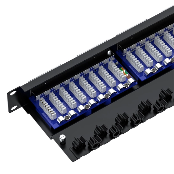
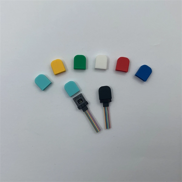
Dimensions of Optical Cable Relay Frames for Wind Power Generation
Based on their structure, ODFs are classified into three main categories: Wall mount ODF, Floor mount ODF, and Rack mount ODF. This type of ODF is ideal for managing small counts of fiber distribution. Prysmian Group is specialized in the design, manufacture and delivery of customized cable sets with various terminations. Different applications require different designs. For special application like EMC or hot oil. Wire and cable systems are the backbone of wind turbine installations, handling both the muscle (electricity) and the brains (data and control). It. The Norden High Density Floor Standing Fibre Optic Distribution Frame is a durable and versatile solution designed for efficient fibre management in high-demand environments. Wheneve handle up to 66 kV between the nacelle- based transformer and the s weigh half as much, making them cheaper, and easier to handle and install in high towers. Nexan in the nacelle, Nexans pr duces LV.
[PDF Version]
-
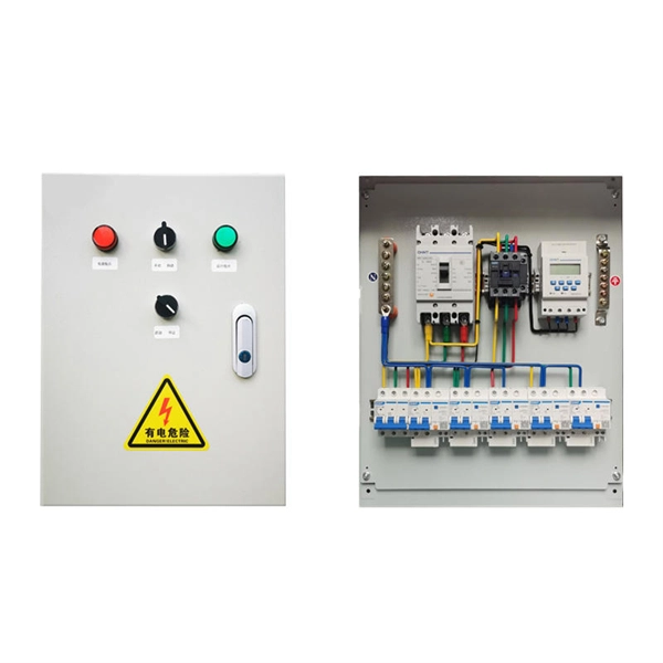
Photovoltaic combiner box energy-saving type for relay protection
By centralising connections and integrating protective components, a solar combiner box reduces balance-of-system (BOS) costs, simplifies installation, and significantly enhances the safety and reliability of the entire PV array. Modern solar power stations—from residential rooftops to 1500V industrial arrays—depend heavily on high-quality electrical enclosures, advanced protection components, and intelligent data systems to maintain long-term reliability. They enable centralized management in large-scale and remote installation ity), equipment aging, and poor installation practices. As solar projects grow, so does the wiring complexity. By bringing together multiple circuits, the combiner box also becomes a natural point for overcurrent protection.
[PDF Version]
-
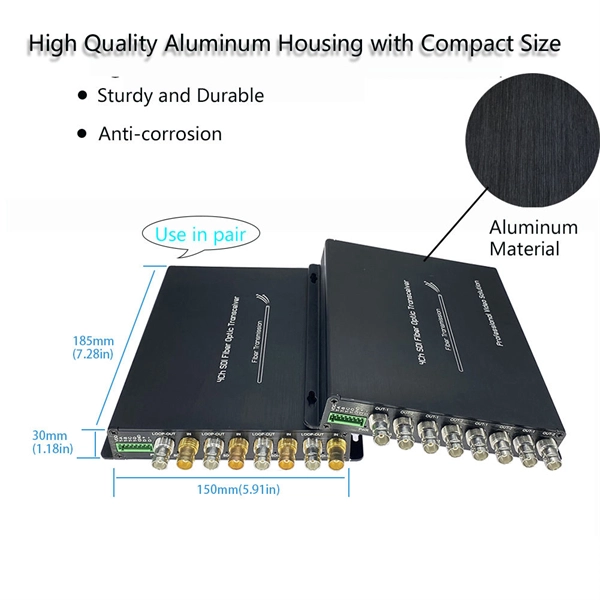
Testing of Optical Digital Relay Protection
Our relay protection tester offers comprehensive testing for both optical digital and traditional protective devices. It's ideal for power plants, substations, equipment manufacturers, and institutions needing relay protection evaluations. They are like the “eyes” and “nerves” of the system, constantly monitoring the health status of the power grid and quickly responding to faults to ensure the safety of personnel and equipment. To ensure the. This product integrates an optical digital network signal analyzer and an optical digital relay protection tester. Comprehensive and practical testing functions, supporting AC tests, group tests, status sequences, phase verification, polarity, virtual terminals, differential protection, distance. IEC Standard 61850 Optical Digital Relay Protection Test System GDJB-61850 Product Description developed this new portable product.
[PDF Version]
-

Installation of Relay Protection Transformers in Tunisia
Abstract: Guidelines for protecting three-phase power transformers of more than 5 MVA rated capacity and operating at voltages exceeding 10 kV is provided to protection engineers and other readers in this guide. Thus, 33 kV network has an effectively earthed neutral (MALT) according to North American standard. criteria for protection schemes. Transformer failure can have severe consequences: Transformer. In this paper, we were interested in the<br> harmonization of the protection plan settings in order to ensure a<br> perfect selectivity and a better continuity of service on the whole of<br> the network. The study focuses on harmonizing protection settings in Tunisia's medium voltage distribution. Track the status of your Support request online. An overview of your request can be found here: This manual describes the functions for transformer protection. The pre-configured RET670 variants.
[PDF Version]
-
Direct Sales of Ethiopian Relay Protection Devices
Find and discover Relay buyers & importers for all products in Ethiopia, featuring details on their shipment activities, trade volumes, trading partners, and more. How does 6Wresearch market report help businesses in making strategic decisions? 6Wresearch actively monitors the Ethiopia Protective Relays Market and publishes its comprehensive annual report, highlighting emerging trends, growth drivers, revenue analysis, and forecast outlook. Our insights help. This is a list of Companies and Businesses in Ethiopia that Import and Supply Electronics & Parts A. More Details AB SQUARE INDUSTRIAL ENGENERING Mobile : +25191120. Meakida MMA-250S IGBT Inverter Welding Machine Advanced IGBT Technology አስተማማኝ እና ቀልጣፋ የብየዳ ስራን *. SolarMax Solar Energy Kit –4 LED lamp Reliable Power, Anytime, Anywhere High-Efficiency Solar. This figure reflects the total revenues of producers and importers (excluding logistics costs, retail marketing costs, and retailers' margins, which will be included in the final consumer price). View all relay suppliers based on products in Ethiopia.
[PDF Version]
-
PSCAD Relay Protection Experiment
Abstract – This paper studied the modelling of 132/33/11kV overcurrent protection by using PSCAD software. The objective of this project is to compare between IEC 60255 Standard and IEEE C37. 112 Standard overcurrent relay response time in the event of fault current. Four transmission line PSCAD functions are used to model two 100km transmission lines and simulate faults along the lines. Tline1+Tline2=100km and Tline3+Tline4=100km. To simulate a fault at 35km, Tline1 is set to 35 and Tline2 to 65, and the. Welcome to this PSCAD Tutorial! In this video, I'll guide you through the process of implementing overcurrent relay protection in PSCAD, a powerful tool for simulating and analyzing power system protection schemes. Our engineering services help utilities, OEMs, and renewable developers simulate real-world contingencies and.
[PDF Version]
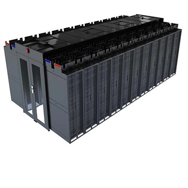
Telecom Racks & Cabinets
19-inch racks, wall-mount cabinets, open frames with high load capacity and seismic rating.
Outdoor Climate Cabinets
IP55/IP66 outdoor enclosures with integrated cooling/heating, -40°C to +55°C operation.
Smart PDUs & Power Distribution
Intelligent PDUs with remote monitoring, per-outlet switching, and environmental sensors.
Shelters & Network Cabinets
Prefabricated telecom shelters, emergency comms shelters, and network cabinets with cable management.