-
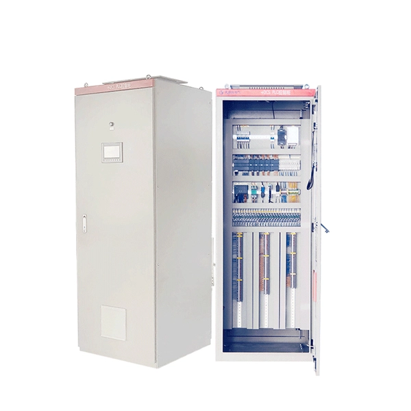
How to wire a power distribution box with a surge protection circuit
In this video, I'll walk you through the process of wiring and installing a Surge Protection Device (SPD) in a Main Distribution Board. Surges may occur due to lightning strikes, power interruptions, or grid switching activities, causing a sudden spike. A single power surge can destroy your TV, computer, or even your entire electrical system within seconds. Protect your electrical system from power surges and lightning strikes by following this simple and clear wiring diagram for an effective SPD setup. more. Locate the SPD as close as possible to the panel to be protected.
[PDF Version]
-
How to configure relay protection time limit
The time delay of zone 2 and zone 3 elements should be set to coordinate with time-step protection at both the remote and local buses. This allows time for the remote zone 1 element to pick up, plus breaker operating time. Plug Setting Multiplier (PSM) indicates how many times the determined relay secondary current (typically the CT secondary) exceeds the relay pickup (plug) current. It is the key quantity utilized in IDMT. Use this Protection Relay Setting Calculator to calculate pickup current, time multiplier settings (TMS), operating time, coordination time interval (CTI), and plug setting multiplier (PSM) using fault current, CT ratio, and IEC 60255 curve parameters. These calculations are critical in industrial. To configure protective devices such as making a relay setting, having all the consideration of the fault severity and decision-making time, it is important to know parameters, rules, and protection zone so that the reliability of the power system having continuous supply, is not compromised. set to clear. Distance relays measure impedance (Z = V/I) to detect faults.
[PDF Version]
-
Special Equipment Relay Protection
They protect assets like generators, transformers, transmission lines, motors, and feeders. Automation: Logic, sequence of events, programmable. SEL relays detect faults and other abnormal conditions in electric power systems and initiate protective actions to maintain system stability and safety. From overcurrent to arc flash protection, LPCTs, LPVTs, redundant Ethernet communication and. Eaton's protective relays provide you with unique microprocessor-based devices that eliminate unnecessary trips, mitigate arc faults, protect motors and breakers, and provide system information to help you better manage your system. Not finding the product that you're looking for? View legacy accessories products. Although failure of a protective relay system may have severe local or regional impacts, most protective relay systems are not required to operate to prove they are in working order.
[PDF Version]
-

Does relay protection require a microcontroller
Microprocessor-based relays (also known as digital relays) use a microprocessor as the main processing element to perform protection functions. Here is a simple point-by-point explanation of their working principle:relay protection; automation; control; IEC-61850; microcontroller; programmable logic; algorithms. Relay protection is the main form of electrical automa-tion, without which normal and reliable operation of modern electric networks and systems are impossible. My particular use case is for an electric guitar effect pedal, i. stompbox, but I think the concepts apply to hifi designs as well (e. Abstract - In this project microcontroller 8051 was used for comparisons between set Impedance and calculated Impedance for based distance relay of the protection of transmission line, based on that trip signal is send to circuit breaker., Arduino, ESP32, Raspberry Pi Pico) is a fundamental skill for switching high-voltage devices (like lights, motors, or appliances) safely. Here's a step-by-step guide: 1.
[PDF Version]
-

What do relay protection workers mainly do
Protective Relay Technicians are responsible for installing, testing, maintaining, and troubleshooting protective relay systems used in electrical power systems. These systems ensure the safety and reliability of power grids by detecting faults and initiating protective actions. They focus on the system protection and control of substation equipment.
[PDF Version]
-

Best protection method for relay protection
Trip Initiation: Sends a precise command to circuit breakers for immediate fault isolation. What measures can be taken to protect the relay itself and handle electrical surges and spikes in an industrial environment? Typically, I place a flyback diode on the coil to prevent back EMF. In one circuit, we've used an NTC to prevent inrush current. The use of snubbers, varistors, Zener diodes. Protective relays and devices have been developed over 100 years ago to provide “lastline”of defense for the electrical systems. It emphasizes selectivity, coordination, fault response, and system behavior rather than individual relay devices.
[PDF Version]
-
How to learn relay protection professional skills
Training for relay testing focuses on imparting essential theoretical knowledge, practical skills, and real-world applications. Equip your team with critical skills to enhance power system reliability and ensure operational safety through expert-led, hands-on training. Our program combines. The Hands-On Relay School is a professional development short course that trains protective relay technicians, electrical/power plant technicians, engineers, and protective relay test specialists. Throughout the school students exchange ideas, resolve problems in open forums, and learn preventative. ABB's Digital Substation Products training and learning centers offer a wide range of training opportunities to ensure you get the most out of your digital substation product, with a special focus on Relion® protection and control relays. Digital substations require them to develop a keen understanding of IED (Intelligent Electronic Device) communications over Ethernet and grow expertise in virtual protection and control environments.
[PDF Version]
-
Residual current protection settings for secondary distribution boxes
A residual-current device (RCD), residual-current circuit breaker (RCCB) or ground fault circuit interrupter (GFCI) is an electrical safety device, more specifically a form of Earth-leakage circuit breaker, that interrupts an electrical circuit when the current passing through line and neutral conductors of a circuit is not equal (the term residual relating to the imbalance), therefore indicating curr. Purpose and operationRCDs are designed to disconnect the circuit if there is a leakage current. In their first implementation in the. with incorporated RCD are sometimes installed on appliances that might be considered to pose a particular safety hazard, for example long extension leads, which might be used outdoors, or garden equ. A pure RCD will detect imbalance in the currents of the supply and return conductors of a circuit. But it cannot protect against overload or like a fuse or a miniature circuit breaker (MCB) does (except for. The diagram depicts the internal mechanism of a residual-current device (RCD). The device is designed to be wired in-line in an appliance power cord. It is rated to carry a maximal current of 13 A and is designe.
[PDF Version]
-
Relay protection is a delicate matter
Protection relays are a very important part of electrical systems. They mostly play the role to prevent the circuits from overcurrent. Overcurrent causes a lot of problems due to thermal heating, which damages the components quickly. In electrical engineering, a protective relay is a relay device. A protective relay is an intelligent device that senses abnormal electrical conditions, such as overcurrent, under-voltage, or frequency deviations. The selection and applications of.
[PDF Version]
-
Discussion on the Future Applications of Relay Protection
The Current Situation and Emerging Trends in Relay Protection - Digital relay protection is evolving with AI and machine learning to offer intelligent fault detection, prediction, and dynamic system adaptation, while also incorporating enhanced cybersecurity and advanced. The Current Situation and Emerging Trends in Relay Protection - Digital relay protection is evolving with AI and machine learning to offer intelligent fault detection, prediction, and dynamic system adaptation, while also incorporating enhanced cybersecurity and advanced. Relay protection systems are essential in maintaining the safety and reliability of modern electrical grids. As technology advances and grids become smarter, the tools used to test and maintain these systems, such as the relay test set, are evolving to meet new challenges. This article explores the. Relay protection plays a crucial role in ensuring the safety and reliability of electrical power networks.
[PDF Version]
-
Calculation of Line Relay Protection Settings
Use this Protection Relay Setting Calculator to calculate pickup current, time multiplier settings (TMS), operating time, coordination time interval (CTI), and plug setting multiplier (PSM) using fault current, CT ratio, and IEC 60255 curve parameters. This paper was presented at the 68th Annual Conference for Protective Relay Engineers and can be accessed at: For the complete history of this paper, refer to the next page. This standard mandates that generator, transmission, and distribution owners establish a process for developing new and revised protection settings and properly coordinate their systems wi h interconnected utilities as part of Requirement 1. T ve. Protection Settings Calculations for Lines i. These calculations are critical in industrial. Distance relays measure impedance (Z = V/I) to detect faults. Consequently, it is shown the method of calculation for a particular power line a d performed the calculation for setting the distance protection.
[PDF Version]
-
Reasons for Relay Protection Current Difference
Static Relays: Use electronic components without moving parts. The aim of this technical article is to cover the most important principles of four fundamental relay protections: overcurrent, directional overcurrent, distance and differential for transmission lines, power transformers and busbars. Overcurrent protection This scheme is based on the intuition that, faults typically short circuits, lead to currents much above the load. Protective relays can be classified based on their operating principle, construction, or function: 1. The potential transformers (PTs) and current transformers (CTs) usually produce electrical signals which monitor the state of current and voltage in a system. It offers improved sensitivity and stability compared to other differential relays and is commonly used to.
[PDF Version]
-
Relay protection in incoming line cabinet
Implementation: Install one or more high-sensitivity leakage current protection relays on the incoming line side of each terminal distribution box (such as a lighting box or socket box). This article will introduce the subway station power distribution system from definition, components, Load. Two types of characteristics are offered for application as follows: Quadrilateral characteristics Mho characteristics are very much preferred for EHV system due to the inherent high speed and characteristics expansion quality. Therefore, Mho characteristic has been selected for phase faults and. The selected protection principle affects the operating speed of the protection, which has a significant im-pact on the harm caused by short circuits. The faster the protection operates, the smaller the resulting ha-zards, damage and the thermal stress will be. The group of relay protection includes RPA cabinets, operational current cabinets, own-use cabinets. Ratings and Protection Facilities of Main Incoming Circuit Breaker (MICB) Where the supply is to be taken directly from CLP transformer, the MICB shall be of draw-out type and rated at 40kA at low voltage.
[PDF Version]
-
Top 10 Relay Protection Testers
High-precision 6-phase testers (e., ZX-7000, UHV-1200) dominate the premium segment ($5k-22k), offering 0. 1% accuracy for critical transmission applications. 5k) like HZJB-I provide optimal cost-efficiency for distribution networks. They are built to sense faults and to help in the operation of circuit breakers. Hence, the relays are used in many different. A malfunctioning relay is often the silent culprit behind a car that won't start or a cooling fan that refuses to kick on. Investing in a dedicated relay tester simplifies the. The SMRT410 and 410D Megger relay test system is a multipurpose, lightweight, field portable test set capable of testing a wide variety of electromechanical, solid state, and microprocessor-based protective relays, motor overload relays, and similar protective devices. These devices typically test single-.
[PDF Version]
-

Disconnection time of the three-level protection of the distribution box
In TN systems, the disconnection time must not exceed 5 s; in TT systems, the disconnection time must not exceed 1 s (see Regulations 411. Automatic Disconnection of Supply (ADS) In general, there are two aspects involved with this protective measure: – Basic protection is used to prevent contact with live parts, and – Fault protection is provided by the protective earthing system and automatic disconnection in case of a fault. This can be confirmed by ensuring the. For electricians in the field, verifying a compliant service disconnect installation is a common task. Follow these steps to ensure the setup meets NEC requirements: Locate the Service Point: Identify where the utility's conductors connect to the premises wiring, whether from a service drop or. The handbook describes various power distribution system constructions and elements there-of, technical considerations, distribution automation infrastructure and functionality, communication aspects, special automation applications and life cycle aspects. (If these areas are accessible to other than pedestrian traffic, then one of the other conditions applies).
[PDF Version]
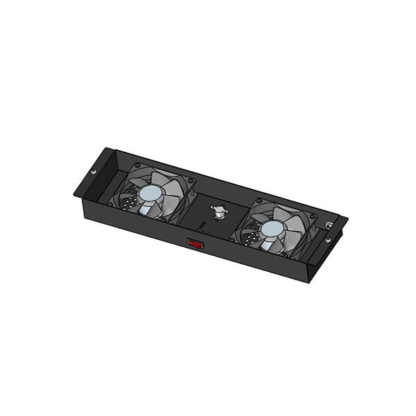
Telecom Racks & Cabinets
19-inch racks, wall-mount cabinets, open frames with high load capacity and seismic rating.
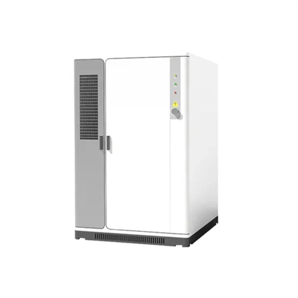
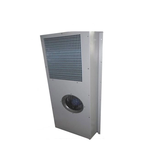
Outdoor Climate Cabinets
IP55/IP66 outdoor enclosures with integrated cooling/heating, -40°C to +55°C operation.
Smart PDUs & Power Distribution
Intelligent PDUs with remote monitoring, per-outlet switching, and environmental sensors.
Shelters & Network Cabinets
Prefabricated telecom shelters, emergency comms shelters, and network cabinets with cable management.