-
Multimode fiber optic patch cord return loss
For multimode fiber, the loss is about 3 dB per km for 850 nm sources, 1 dB per km for 1300 nm. 5 dB/km max per EIA/TIA 568) This roughly translates into a loss of 0. In optical fiber communications, insertion loss and return loss are two important indicators for evaluating the quality of Fiber Optic Cable Assemblies, such as optical fiber connectors, optical jump fibers and pigtails. This article explains their concepts, standards, testing methods, and FiberMania's quality assurance workflow to ensure optimal network performance. Fiber optic patch cords are crucial components in. Fiber Optic Patch Cords are designed to interconnect, or cross-connect fiber networks within structured cabling systems for data centers, Broadband CATV, Passive Optical Networks (PON), WDM or DWDM multiplexing, FTTH, and voice services in ATM and SONET metropolitan and access networks. Unlike backbone trunk cables—which are typically multi-fiber. To be able to judge whether a fiber optic cable plant is good, one does a insertion loss test with a light source and power meter and compares that to an estimate of what is a reasonable loss for that cable plant.
[PDF Version]
-
Are fiber optic connectors prone to connection loss
In FTTH and FTTx access networks, optical connectors are often treated as standardized, low-risk components. Many FTTH networks technically meet design. optic connector apart in terms of its merits? The primary purpose of a fiber optic connector is to terminate the ends of fiber optic cables, ensuring they can be int rconnected reliably with minimal optical loss. This article explores various connector types—such as SC, LC, FC, ST, APC, and UPC—and analyzes how their design and polishing affect IL and RL performance. Insertion Loss (IL): Measures the. To determine the power budget and power margin needed for fiber-optic connections, you need to understand how signal loss, attenuation, and dispersion affect transmission. Understanding the causes of signal loss and implementing mitigation strategies is essential for maintaining network efficiency. From infrastructure planners to telecom engineers.
[PDF Version]
-
Are fiber optic quick connectors prone to loss
The typical insertion loss range for fiber optic fast connectors falls between 0. 5dB, highlighting their ability to maintain signal integrity while minimizing power loss during transmission. They are commonly applied in FTTH, data centers, telecom networks, and ODN systems, where quick field termination and low signal loss are crucial. 25 mm zirconia ferrule, making it ideal for high-density patch panels. This article explores various connector types—such as SC, LC, FC, ST, APC, and UPC—and analyzes how their design and polishing affect IL and RL performance.
[PDF Version]
-
What to do if the fiber optic cable splice loss is too high
If high loss persists, inspect the splicer's alignment system. Clean the V-grooves and objective lenses with appropriate cleaning sticks and isopropyl alcohol. Dirt or dust on the fibre ends is one of the most common causes of high splice loss. Fusion splicers have settings that must be tailored to your fibre type and condition. Modern fiber optic networks usually keep splice loss low, as shown below: You should know that each splice can add 0. Understanding its causes and solutions is critical for reliable fiber optic installations. Poor Fiber Cleave: Angled or chipped cleaves prevent proper. Neglecting minor problems can lead to higher splice losses, increased signal attenuation, and long-term damage to fibre networks. This. One problem I continue to see is unexpected high loss during spicing between exchange-to-exchange network, particularly in the feeder and backbone segments, which can seriously impact the performance of the PON networks.
[PDF Version]
-
Huawei 2500 Fiber Optic Cable Loss
For multimode fiber, the loss is about 3 dB per km for 850 nm sources, 1 dB per km for 1300 nm. 5 dB/km max per EIA/TIA 568) This roughly translates into a loss of 0. Optical fiber loss refers to the decrease in optical power due to absorption and scattering after optical signals are transmitted through optical fibers. When implementing optical fiber communication, a key challenge is minimizing the loss of signals within the fiber. This is caused by the. To be able to judge whether a fiber optic cable plant is good, one does a insertion loss test with a light source and power meter and compares that to an estimate of what is a reasonable loss for that cable plant. Use this worksheet to input values for all variables that will impact your system's performance. Signal loss in Fiber Optic networks can make data slow. It can also break your connection. You should fix it fast to get speed.
[PDF Version]
-
How to calculate the test loss of optical cable connectors
To calculate fiber optic link loss budget: First, determine total fiber attenuation by multiplying distance by attenuation coefficient. Add connector losses (typically 0. To be able to judge whether a fiber optic cable plant is good, one does a insertion loss test with a light source and power meter and compares that to an estimate of what is a reasonable loss for that cable plant. Over 95% of global internet traffic travels through fiber optic cables. At TREND Networks, we are frequently asked how much loss is allowed when conducting testing on fiber optic cabling. Unfortunately, it is not a simple answer and depends on several factors. First, you should be aware of the fiber loss formula: The Total Link Loss = Cable. Use this worksheet to input values for all variables that will impact your system's performance.
[PDF Version]
-
Multimode fiber optic splice loss standard
For multimode fiber, the loss is about 3 dB per km for 850 nm sources, 1 dB per km for 1300 nm. 5 dB/km max per EIA/TIA 568) This roughly translates into a loss of 0. Splicing is required to create a continuous path for light transmission from one fiber to another. Two different methods exist for splicing fibers: Typical splice loss values (the measure of loss in optical power across the splice point) are usually lower for fusion splices (typically less than 0. 1. To be able to judge whether a fiber optic cable plant is good, one does a insertion loss test with a light source and power meter and compares that to an estimate of what is a reasonable loss for that cable plant. The estimate, called a "loss budget" is calculated using typical component losses for. Acceptable dB loss for fiber depends on the component you're measuring: a single mated connector pair should lose no more than 0. 75 dB, a fusion splice should stay under 0. 5 dB per kilometer depending on the type and wavelength. The Contractor must utilize the correct equipment and testing techniques to gain acceptance, or the work cannot be approved. Optical fiber splicing is a critical.
[PDF Version]
-
South Korean Fiber Optic Cable Loss Standards
Multimode Fiber: Typical allowable loss is 2. 9 dB for short-distance installations (100–300 meters). To be able to judge whether a fiber optic cable plant is good, one does a insertion loss test with a light source and power meter and compares that to an estimate of what is a reasonable loss for that cable plant. The estimate, called a "loss budget" is calculated using typical component losses for. Using an optical power meter and light source or OLTS (Optical Loss Test Set), Tier 1 Certification can be performed against industry standard limits for cable and connectors. Fiber optic testing of a newly installed system not only verifies that the system meets its design requirements, but also creates a performance baseline for all future testing and troubleshooting of t at system. The Contractor must utilize the correct equipment and testing techniques to gain acceptance, or the work cannot be approved. This testing. Fiber Loss Limits Understanding fiber loss is vital in maintaining a reliable, efficient network. Fiber loss, or attenuation, refers to the reduction in optical power as light travels through a fiber optic cable.
[PDF Version]
-
Low loss hollow fiber
Unlike traditional fibers that guide light through solid silica cores, HCF channels light through an air-filled central core, leveraging photonic bandgap or anti-resonant structures to minimize signal loss and dispersion. This study innovatively presents a hollow-core anti-resonant fiber integrating double-tube nesting and a single-layer anti-resonant wall. Featuring an exclusive two-layer cladding configuration along with an outer cladding circular ring, it differs significantly from traditional fibers. In practice HCF is built as a microstructured glass “jacket” surrounding a central air channel. Light is guided not by total internal reflection in glass but by photonic-bandgap or. In the ever-evolving landscape of fiber optic technology, hollow core fiber (HCF) emerges as a groundbreaking innovation, challenging the decades-long dominance of solid-core fibers. Additionally, the variations in the wall thickness.
[PDF Version]
-
Optical Amplifier Return Loss
Optical Return loss is defined as the ratio of incident to reflected power, expressed in decibels. This equation shows that a smaller reflection means a larger value of optical return loss. The term ORL is used to describe the ratio of relative magnitude of the cumulated back reflectance or multiple Fresnel events and backscattered signal power to the optical. Reflectance (which has also been called "back reflection" or optical return loss) of a connection is the amount of light that is reflected back up the fiber toward the source by light reflections off the interface of the polished end surface of the mated connectors and air. In high-speed single-mode links, DWDM systems, and even certain high-power laser applications, reflection. This AE Note explains the differences between Optical Return Loss (ORL) and Back Reflectance in fiber optic systems. The driving force behind understanding these topics is the ever-increasing high-speed transmission systems and the use of DWDM in the industry today. This topic is becoming critical. Beginning with software release 1.
[PDF Version]
-
1 to 32 splitter insertion loss
A 1:32 splitter divides input power by ~32 (adding ~15dB of insertion loss), so the remaining power supports signals up to 20km. Calculate insertion loss for passive optical splitters in PON and distribution networks. Power is divided equally among output ports. This is a single-direction budget estimate; downstream and upstream wavelengths or optical classes may. Optical insertion loss refers to the signal loss resulting from the insertion of components such as connectors or splices in an optical fiber system. Common values: 2, 4, 8, 16, 32, 64.
[PDF Version]
-
Performance Comparison of Low Insertion Loss Splitter Remote Monitoring Type and Selection Guide
This guide focuses on two critical aspects of optical splitters that define FTTH performance: split ratios (how signals are divided) and splitting architectures (how splitters are deployed). In fiber-optic networks like FTTx and PON, PLC splitters are key components for distributing optical signals to multiple users. However, each splitter has complex parameters, including insertion loss, return loss, polarization-dependent loss, and uniformity. They have been used since the 1980s to create networks and provide the technology for today's passive optical networks used in fiber to the home. Planar Lightwave Circuit (PLC) splitters are essential passive devices in modern fiber-to-the-home (FTTH) networks. Although often viewed as a simple passive device, the choice of splitter type, split ratio, and connector interface has a direct impact on network performance, scalability, installation efficiency, and long-term operational cost.
[PDF Version]
-
How to calculate the loss from cutting a telecommunications fiber optic cable
The loss budget formula adds fiber length, connector/splice losses, and a safety margin (usually 3 dB). • Use worst-case estimates and validate with actual measurements. A tool that computes how many fibers fit in a circular bundle and splits them into user-defined segments for cable-assembly planning. Key Parameters: • Center Diameter, Fiber Diameter, Packing Efficiency, Section Count Calculation: Visualization: • Color-coded radial diagram with per-section. To ensure a fiber optic link operates correctly, you need to calculate its loss, power budget, and power margin. The calculation methods are as follows. In fiber optic cabling, it is often necessary to calculate the maximum loss over a certain length of line. After entering your values, please ensure you click the 'Calculate Link Loss' button at the bottom of the page to generate your total link loss.
[PDF Version]
-
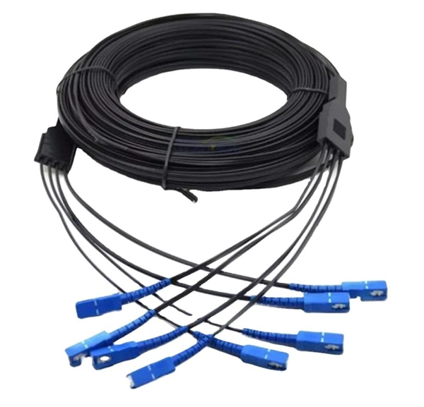
What are the uses of SC fiber optic cold connectors
SC connectors are commonly used in FTTH installations, ensuring efficient connections from central offices to individual homes. Cost-effective compared to smaller form-factor connectors. Durable and suitable for field deployments. They. This overview of what fiber optic cables are used for in industrial systems is a useful companion if you're mapping where fiber belongs versus copper. Port-first buying: The team matches the connector shape but misses singlemode versus multimode. Of the more than a dozen types of fibre-optic connectors available, the four most commonly used today are.
[PDF Version]
-
All Connection Methods for Fiber Optic Cold Connectors
It explains all major connector types (LC, SC, MPO/MTP, ST, FC, rugged industrial connectors), the differences between simplex/duplex, single-mode/multimode, boot types, polish types (UPC/APC), and termination methods. This blog introduces 4 Methods of fiber connections, including: Active Connection, Cold Splicing, Fusion splicing and Physical Connection. Active Connection Active connection utilizes various fiber optic connectors (plugs and sockets) to connect site-to-site or site-to-cable. Unlike fiber splicing, which is permanent, connectors allow for easy connection and disconnection of cables, making them ideal for maintenance and flexibility in. What is a Fiber Connector? The fiber connector is called a fiber optic or optical fiber connector.
[PDF Version]
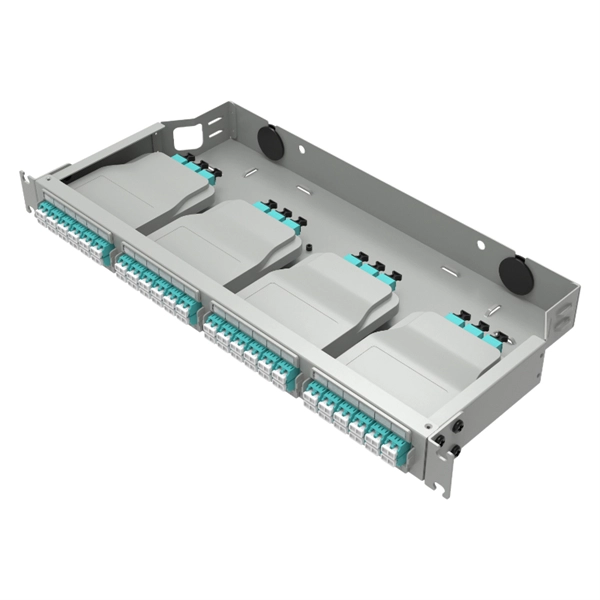
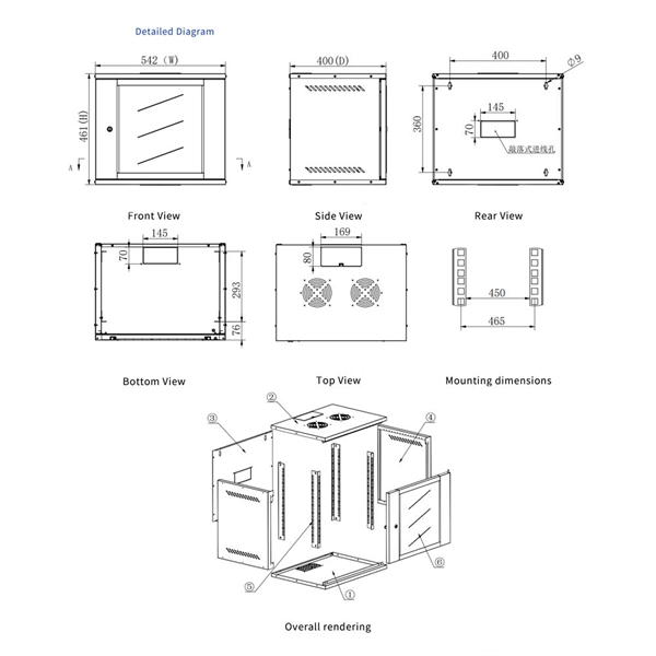
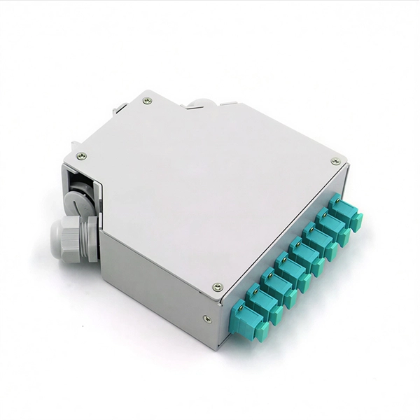
Telecom Racks & Cabinets
19-inch racks, wall-mount cabinets, open frames with high load capacity and seismic rating.
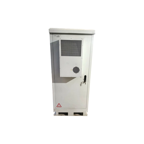
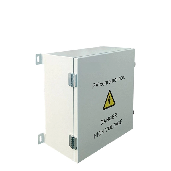
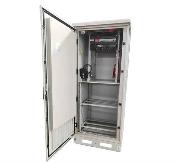
Outdoor Climate Cabinets
IP55/IP66 outdoor enclosures with integrated cooling/heating, -40°C to +55°C operation.
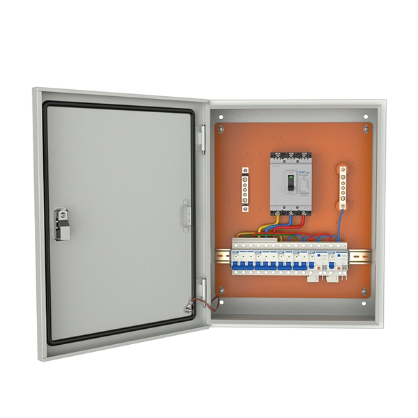
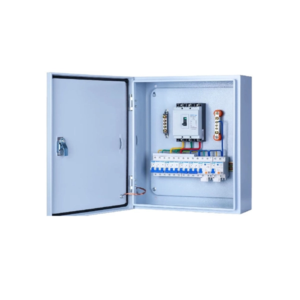
Smart PDUs & Power Distribution
Intelligent PDUs with remote monitoring, per-outlet switching, and environmental sensors.
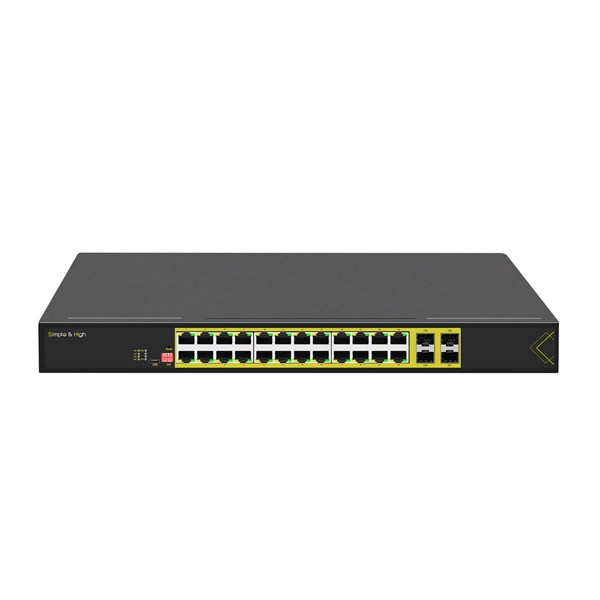
Shelters & Network Cabinets
Prefabricated telecom shelters, emergency comms shelters, and network cabinets with cable management.