-
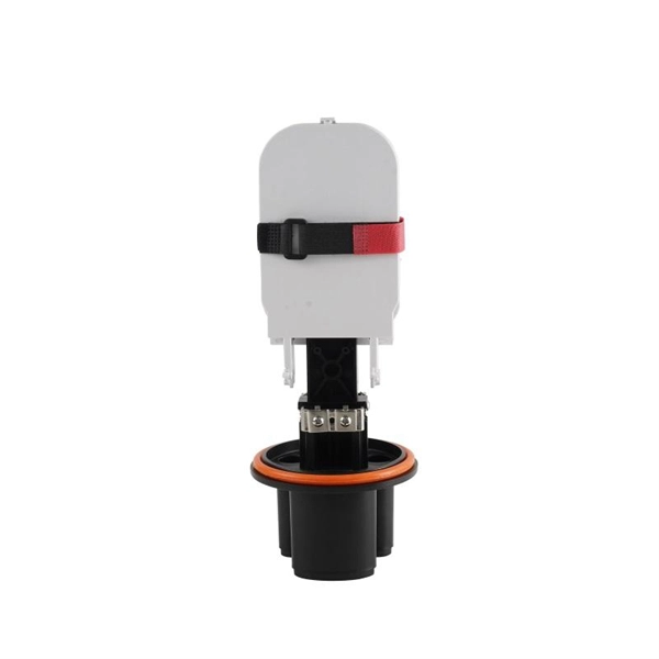
Does the optical fiber need to be wrapped with tubing
Spiral cut tubing (also known as spiral wrap) helps protect and bundle optical fibers for communication applications. PTFE and FEP spiral wrap are. The Installation After the process of designing fiber optic networks is completed, the next step is to install it. What do we mean by the “installation process?” Assuming the design is completed, we're looking at the process of physically installing and completing the network, turning the design. Fiber optic installation delivers unmatched network performance for modern businesses, providing greater bandwidth capacity and superior resistance to electromagnetic interference compared to traditional copper cables. Local company practices and/or vendor specifications may be in place concerning cable access and how it relates to a. When installing optical fiber cables, the requirements for wiring methods are located in Art. 770 references sections in Chapter 2 and Art. 22, which applies when. Fiber optic cable may be installed indoors or outdoors using several different installation processes.
[PDF Version]
-
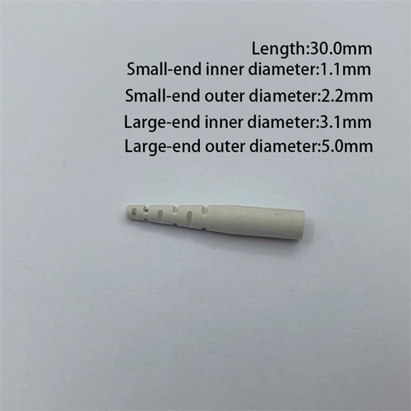
Belarusian large-core optical fiber 1310nm
In this article, we explore the key characteristics, common applications, and important comparisons related to 1310nm optical modules. Used for medium-distance links in city networks. As part of the O-band (1260–1360 nm), it balances low dispersion, stable performance, and cost efficiency. This makes it widely adopted in data centers, enterprise backbones, and metro access. The product features an SFP+ package with an LC connector, a 1310nm DFB laser with a PIN photodetector, and supports up to 20km transmission on SMF with power dissipation under 1W. Or It is also suited for analog fiber transmission. Pricing (USD) Filter the results in the table by unit price based on your quantity. A. 10GBASE-LRM SFP+ Transceiver Module 1310nm 220m - FS. com FS United StatesFREE SHIPPING on Orders Over US$79 Contact Us United States / $ USD Sign in Sign up Search Recent Searches Change FREE SHIPPING on Orders Over US$79 United States HomeOptical Transceivers10/25/40/100G. SFP+, 1310nm, LR SMF 10km, 10G DDM, Corning 1LAN-SFPP-10GB-LR Compatible Integra manufactures the highest quality SFPP transceivers in the industry, designed to be 100% interoperable with all OEM platforms.
[PDF Version]
-
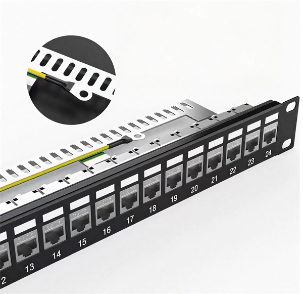
How many fiber optic cores can a single optical module connect to
A simple rule is that each device needs two cores—one for sending and one for receiving data. Start by counting how many devices you're connecting. (actually use a four core optical cable) This is because apart from one-core optical fiber, there are basically no optical cables with an odd number of cores, such as three-core, five-core, etc. It is worth. The total number of cores for a 1pc fiber patch cable is calculated as the number of branches multiplied by the number of cores per branch (if there are no branches, the number of branches = 1). In the context of accelerating digitalization, the rational. o In optical modules, "core" refers to the light-transmitting channel in the fiber.
[PDF Version]
-
Does a fiber optic splitter need an optical module
The optical transceiver module (like an SFP, SFP+, or XFP module) in the OLT is the laser source that generates the initial light signal. This high-power signal is transmitted down the single fiber. When it reaches the optical splitter, the signal is divided and. These unassuming devices enable a single optical signal to be divided into multiple paths, making them indispensable for sharing network resources efficiently—from residential FTTH (Fiber-to-the-Home) connections to large-scale telecom backbones. This guide demystifies fiber optic splitters. Fiber optic splitter is a passive optical device that includes multiple input and output ends. T PON standards such as GPON, XGS-PON and new 25 and 50G standards. A fiber broadband provider typically determines and overall split ratio for the network, such as 1x32 or 1x64, and uses combinations of splitters to meet that ratio with each PON port. 1x32 splits were common in North America for G-PON architectures. Conversely, it can also combine multiple signals into one.
[PDF Version]
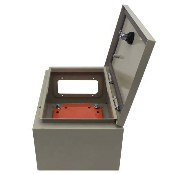
Telecom Racks & Cabinets
19-inch racks, wall-mount cabinets, open frames with high load capacity and seismic rating.
Outdoor Climate Cabinets
IP55/IP66 outdoor enclosures with integrated cooling/heating, -40°C to +55°C operation.
Smart PDUs & Power Distribution
Intelligent PDUs with remote monitoring, per-outlet switching, and environmental sensors.
Shelters & Network Cabinets
Prefabricated telecom shelters, emergency comms shelters, and network cabinets with cable management.