-
High-speed optical fiber connection for IDC data centers DML
This article explains the different types of fiber optic cables used in data centers — from single-mode to MPO/MTP — and why proper selection, installation, and maintenance are crucial for avoiding data loss and downtime. In a Tier III colocation center in São Paulo, replacing legacy copper cabling. Molex provides modular trunks, expanded beam technology and easy-to-service designs that maximize bandwidth per rack unit while simplifying upgrades and troubleshooting. Data centers are driving higher data rates into racks where space is already limited. To support higher bandwidth demands, optical. From AI computing clusters to cloud storage and telecom exchange points, the demand for faster, denser, and more scalable optical networks has never been higher. MicroCore® cabling forms the backbone of high-tech networks installed in applications ranging from the Local Area Network to the most complex DataCenter environments.
[PDF Version]
-
Custom Process for 24-Core Fiber Optic Splices for Data Centers
The diagram of 24 core fiber fusion splicing sequence is an essential tool for engineers in the telecommunications industry. This article provides a detailed explanation of the sequence, covering four aspects: preparation, stripping and cleaning, fusion splicing, and. Whether you need fusion splicing for permanent, ultra-low-loss connections or mechanical splicing for rapid field deployment, our certified technicians deliver factory-quality results on every job — from hyperscale data centers and carrier-grade telecom networks to enterprise campus infrastructure. As networks grow larger, denser, and more complex, fiber optic splicing becomes a critical path activity that directly impacts time‑to‑light, network reliability, and long‑term operating costs. Therefore, we will also touch on cost factors, risk management, and best practices in. Fusion splicing is the bedrock of high-performance fiber optic networks, enabling seamless signal transmission through permanent, low-loss fiber joins. This field technician tutorial shows the real splicing process, core alignment, and best practices to.
[PDF Version]
-
Low-loss certification for optical circulators used in IDC data centers
Here, we present a solution to this issue by realizing low-loss (0. 81 dB), broadband (at least 50 GHz bandwidth) and high-extinction (up to 27 dB) circulators, based on Mach-Zehnder interferometers including so-called fiber null-couplers. An Optical Circulator is a non-reciprocal passive device used in fiber optic communication systems to control the direction of light propagation. Unlike optical isolators that block reflected light, a circulator routes optical signals in a specific order — typically Port 1 → Port 2 and Port 2 →. ACP's Multimode optical circulator utilizes proprietary designs and metal bonding micro optics packaging. It provides low insertion loss, broad band high isolation, low PDL, excellent temperature stability and optical path epoxy free. 24, 2026 /PRNewswire/ -- VIAVI Solutions Inc. (VIAVI) (NASDAQ: VIAV) has announced the DCX 700 tier 1 optical loss test set for testing up to 24 fibers simultaneously.
[PDF Version]
-
Number of 100G optical modules in data centers
The market currently offers several types of 100G optical modules: CXP, CFP, CFP2, CFP4, and QSFP28 modules. CXP modules offer high transmission rates of up to 12×10Gbps and support hot-swapping. Traditional data centers are mainly based on a 10G network architecture. The Cisco 100GBASE Quad Small Form-Factor Pluggable (QSFP) portfolio offers customers a wide variety of high-density and low-power 100 Gigabit Ethernet connectivity options for data center, high-performance computing networks, enterprise core and. This article helps network engineers, field technicians, and procurement leads choose optical modules that will actually survive high-speed rollout. You will get a real deployment case, the exact selection checklist, and troubleshooting patterns seen on live racks. Deploying 100G transceivers is critical for optimizing network scalability, reducing latency, and improving overall operational efficiency. Among the various high-speed optical form factors available today, 100G QSFP28 Transceivers have emerged as the industry standard for delivering reliable, cost-effective 100-gigabit Ethernet links across a wide range of deployment scenarios.
[PDF Version]
-
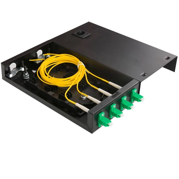
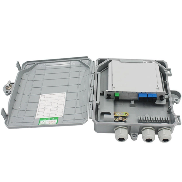
How many ports does the optical fiber splitter distributor have
Featuring 24 fiber ports, comprising 3 inlet, 16 outlets, this fiber optic splitter box ensures seamless connectivity across your fiber optic infrastructure. Cost Efficiency: A single OLT port can serve 8–64 ONTs via a splitter, reducing the number of OLTs, fibers, and deployment labor needed. Passive Operation: Splitters have no active electronics, so they require no power, cooling, or maintenance—lowering operational costs (OPEX) for ISPs. Indoor/Outdoor Wall Mounted, Single Door Fiber Distribution box is ideal for end terminations of fiber optic runs in residential or commercial buildings. Integral gasket seal provides IP65 level of protection. Pre-installed with 24 SC/APC simplex couplers and two 1x8 terminated SC/APC splitters, it effortlessly supports single-mode fiber optic. A fiber broadband provider typically determines and overall split ratio for the network, such as 1x32 or 1x64, and uses combinations of splitters to meet that ratio with each PON port. 1x32 splits were common in North America for G-PON architectures.
[PDF Version]
-
Correspondence between optical cable and optical fiber units
In essence, while optical fiber forms the core technology enabling high-speed data transmission, optical fiber cables are the infrastructure that harnesses and protects these fibers. The different structures of conductors lead to differences between cables, optical cables, and optical fibers. This protective layer shields the fibers from external influences like moisture, temperature variations, and physical stress, ensuring the longevity and reliability of the optical transmission. So optical fiber is the core part of optical fiber cable, optical fiber through some of the components of the protection of the subordinate protective layer constitutes an optical fiber cable. An optical fiber or optical fibre is a flexible, transparent fiber made by drawing glass (silica) or plastic to a diameter slightly. Fiber optic cables and optical fibers are often used interchangeably, but they are not exactly the same thing. In this article, we will explore these differences and shed.
[PDF Version]
-
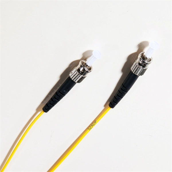
How to connect fiber optic cable to the optical transceiver
Remove protective caps from optical fiber connectors, insert optical fibers into the optical transceiver, and connect the fiber to the peer device. Ensure that the Tx and Rx ports are correctly connected. This guide explores the essentials of SFP connectivity, installation best practices, and how Weunion's. Proper connection of fiber optic cables is essential to harness these benefits fully, as even minor errors can lead to significant performance issues like signal loss. To connect a fiber optic cable to SFP optical module, first ensure the SFP is fully inserted into the network port until it "clicks", then remove the dust caps from both the SFP and the LC fiber optic connector. The USG supports both 1 Gbit/s, 10 Gbit/s, and 40 Gbit/s optical modules. To learn more about the types of fiber optic connectors, click here: Types. In this article, we will guide you through the process of connecting optical fiber cables, step by step.
[PDF Version]
-
Price list for 200GLPO optical modules for data center interconnection
FS offers a growing portfolio of 200/400/800G optical transceiver modules and cables. Click to get your transceiver modules . Transceiver USA's TUSA200GQSFPFR4 optical modules are used in datacenter and enterprise networks. View price, stock and buy direct from Transceiver USA. The super-high density and backwards compatibility can enable high bandwidth and high speed links for data center and cloud networks. Offering flexible 2x100G or 1x200G configurations, our modules are perfectly compatible with major switch brands like Cisco, Arista, and Juniper - the core solution. The TQSFPDD-200G-SR8 is a Eight-Channel, Pluggable, Parallel, Fiber-Optic QSFP Double Density for 2x100 Gigabit Ethernet Applications.
[PDF Version]
-
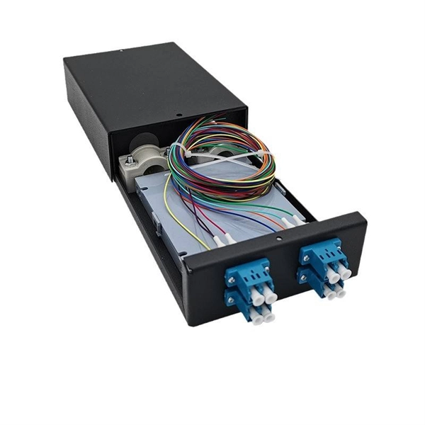
Can a single-mode dual-core optical fiber be split into two cables for use
The answer is yes, and it's a practice widely used in the industry to distribute signals to multiple destinations without degrading the signal quality significantly. There are two primary methods of splitting an optical cable: Passive splitting involves using a specialized device called an optical splitter. Splitters come in various configurations, such as 1x2, 1x4, or 1x8, depending on how many splits are needed. Since BIDI single-fiber uses two separate wavelengths over the same fiber strand, the transmit (Tx) on the media converter at one end of the fiber link matches the receive. These unassuming devices enable a single optical signal to be divided into multiple paths, making them indispensable for sharing network resources efficiently—from residential FTTH (Fiber-to-the-Home) connections to large-scale telecom backbones. This guide demystifies fiber optic splitters.
[PDF Version]
Telecom Racks & Cabinets
19-inch racks, wall-mount cabinets, open frames with high load capacity and seismic rating.
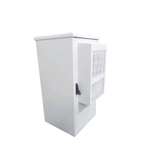
Outdoor Climate Cabinets
IP55/IP66 outdoor enclosures with integrated cooling/heating, -40°C to +55°C operation.
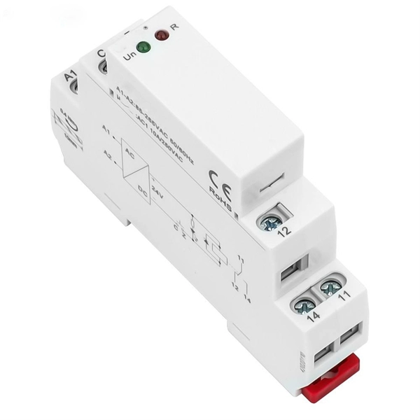
Smart PDUs & Power Distribution
Intelligent PDUs with remote monitoring, per-outlet switching, and environmental sensors.
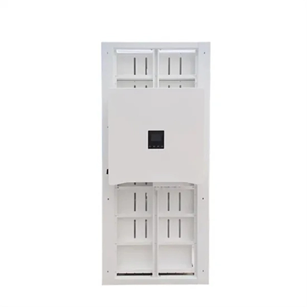
Shelters & Network Cabinets
Prefabricated telecom shelters, emergency comms shelters, and network cabinets with cable management.