-
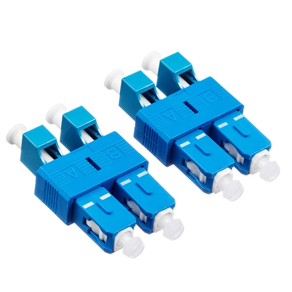
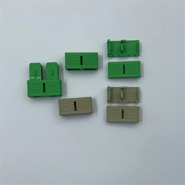
How to tell the front from the back of a fiber optic patch cord
The ferrule end face of the patch cord is ground into different structures. PC, APC, and UPC are three different ferrule polishing methods, representing the structural differences of the front face of the ceramic ferrule. As shown below, the ferrule is the housing for the bare end of an optical. At ZION Communication, we design and manufacture a full range of fiber patch cords for: This guide will help you quickly understand the main types of fiber patch cords and how to choose the right solution for your project – and how ZION can support you with stable quality, flexible customization. Here at Fiber Optic Center, we believe it's important to introduce engineers and technicians to various aspects of the production process to manufacture high-performance, world-class fiber optic cable assemblies. Ideally, your finished fiber optic cable assembly will meet all relevant international. Fiber optic patch cords, also known as fiber optic patch cables or fiber jumpers, are indispensable components in modern optical networks. Fiber optic patch cables are found almost everywhere; cable television networks (CATV), data centers, computer networks, and telephone networks.
[PDF Version]
-
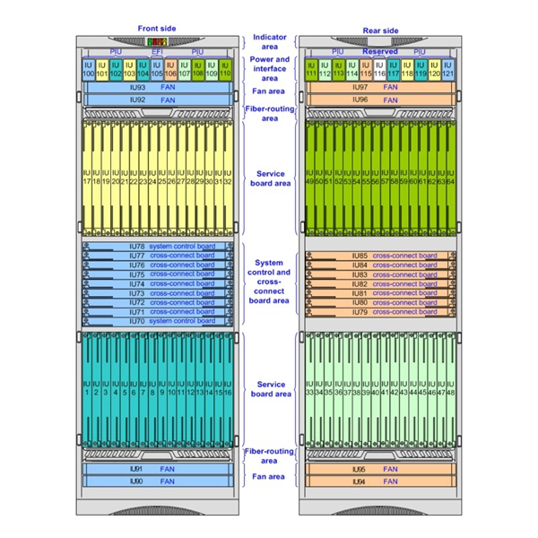
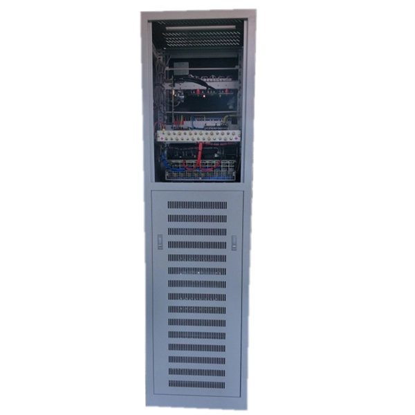
Understanding Base Station Communication Power Systems
From making a phone call in a busy city to streaming videos in remote villages, the ability to stay connected relies on one critical piece of infrastructure: the telecom base station. Often hidden in plain sight on rooftops or towers, base stations are the backbone of. Base stations play a pivotal role in mobile telecommunications, acting as the nexus between users' cell phones and the broader network infrastructure. It acts as a bridge, connecting your phone to a vast communication network to ensure smooth information flow. Understanding which battery chemistries are appropriate is key to avoiding failures and downtime. The transceiver too deals with the power control. Apparatus redeploy. Portable coverage changes block by block. The fixed station remains the anchor point for mobiles, portables, repeaters, dispatch consoles, and any interface into logging, alerting, or dispatch platforms.
[PDF Version]
-
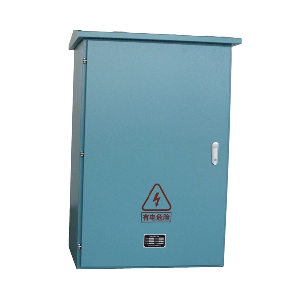
The meter box is the same as the distribution box
The meter box is a special box for electricity metering, such as ammeter, watt hour meter, power meter, etc. It acts as the formal interface between the utility power supply and the consumer's internal electrical system. The distribution box is collectively. The submetering box is slightly different from a distribution box in that it adds a monitoring function to the circuits. They are. The meter box and distribution box are collectively referred to as "three boxes" 1、 Illumination box 2、 Power box 3、 Metering tank The electricity meter installed in the electricity meter box belongs to the "metering box", which has anti-theft devices according to different requirements;. The meter box and the small power distribution unit (SPDU) are two different devices, and their main difference lies in their purpose and function.
[PDF Version]
-

Wiring on the side of the distribution box
Wiring Direction: Wiring between the main circuit breaker and each branch circuit breaker in the box generally goes on the left, and the wiring out of the distribution box generally goes on the right. Binding Requirements: The wires should be bound with. Learn how to wire a distribution box step by step! This video shows real on-site footage of electrical installation, demonstrating safe and standardized wiring methods used by professionals. It takes the incoming power and safely distributes it to different circuits throughout your building. 2 kV on the primary side and step it down to 120V single-phase and 120/240V split-phase for residential applications.
[PDF Version]
-
Wiring port at the bottom of the distribution box
The bottom of the distribution board has two dedicated headers for the secondary transformer and connection to the indoor unit. Furnaces will require the installation of the 50VA transformer when incorporating an electronic air cleaner. Choose the right box based on environment (indoor/outdoor), load capacity, and durability. Check for proper IP/NEMA ratings and material quality. And all the switching and protective devices are installed in the. Connection method: Each switch takes a wire from the incoming point and connects it to the incoming end of the switch, or uses parallel connection to reduce the difficulty of wiring. Wiring Direction: Wiring between the main circuit breaker and each branch circuit breaker in the box generally. An electrical panel box, also known as a breaker box or a distribution board, is a crucial component of any electrical system.
[PDF Version]
-
Adjustable attenuator smart technology vs which has better performance
A good attenuator choice makes the whole system calmer: fewer surprises, fewer reflections, fewer “it only fails at power” mysteries. Choose the topology for the job, then use the calculator to get the numbers. How do I choose between a fixed attenuator, a step attenuator, and a variable attenuator for my system? The three attenuator types serve different purposes and have distinct performance characteristics: (1) Fixed attenuator: a passive device providing a single, permanent attenuation value (1-30 dB. RF attenuators are essential components that reduce signal power, preventing overload and improving the overall performance of communication systems. You'll find them in almost every RF communication setup. RF Attenuators, also known as radio frequency attenuators, are electronic devices designed to reduce the strength of radio frequency signals. This type of component is generally used to balance signal levels in the signal chain, to extend the dynamic range of a system, to provide impedance matching, and to. In RF work, SMA attenuators often play the role of unsung heroes.
[PDF Version]
-
What is the name of the door wire of a three-level distribution box
The neutral wire (white) from the main disconnect terminates at a neutral busbar. The National Electrical Code (NEC) provides comprehensive safety standards for electrical installations, including requirements for electrical panels (main service panels and subpanels or breaker box). NEC Article 408. They are the conductors between the terminals of the service equipment and the service drop, overhead service conductors, service lateral, or underground service conductors. An overhead power connection from the utility. A distribution board (also known as panelboard, circuit breaker panel, breaker panel, circuit breaker, electric panel, fuse box or DB box) is a component of an electricity supply system that divides an electrical power feed into subsidiary circuits while providing a protective fuse or circuit. Distribution boards, often referred to as electrical panels or breaker boxes, serve as the nerve center of any electrical system. Three-phase distribution boards are used in large factories, buildings, manufacturing units.
[PDF Version]
-
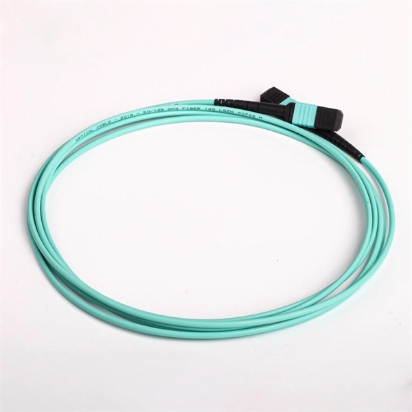
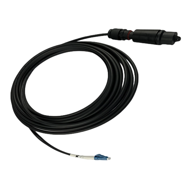
What is the fiber optic cable on the back of the router
It is a 'standard' single-mode fiber cable with an SC-APC connector at the end. You can't 'really' connect it directly to a random consumer router in most cases - it's meant to go into an optical fibre device. We provide bulk fiber patch cords, ONTs, and pre-terminated cables for large-scale FTTH deployments. [Get a Project Quote] Are you ready to unlock the blazing-fast potential of fiber optic internet? The process to connect fiber optic cable to router requires careful attention to detail, but I'll. A fiber cable (drop) is run from a nearby terminal that could be either a pole or an underground box) to your home. it is called what you called it. Why do you want to use your router instead of the one the ISP gave you? That is clearly not an option. Made of strands of glass or plastic thinner than a human hair, the cables transmit data as pulses of light.
[PDF Version]
-
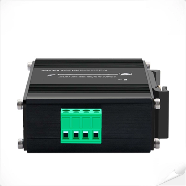
Differences between photoelectric converters and optical modules
The optical fiber media converter is a network interconnection device that realizes the regeneration amplification and wavelength conversion of optical signals, and the optical module is a network interconnection device that realizes the conversion of photoelectric . The optical fiber media converter is a network interconnection device that realizes the regeneration amplification and wavelength conversion of optical signals, and the optical module is a network interconnection device that realizes the conversion of photoelectric . Optical modules and media converters are both key photoelectric conversion devices widely used in fiber optic communication, data centers, enterprise networks, and broadband access systems. Many users are confused about their roles, differences, and connection rules. What are Fiber Transceiver and Media Converter? As an optical device that performs photoelectric. The SFP module is a hot-pluggable optical transceiver used for connecting network switches. It converts electrical signals to optical signals and vice versa.
[PDF Version]
-
Waterproof fiber optic installation tools vs copper cables
Compare fiber optic and copper Ethernet cables across speed, distance, cost, installation difficulty, and use case metrics. Use the interactive scenario selector to find the right medium for your specific network — all processed locally in your browser. Networking cables are the foundation of modern communication systems, connecting devices across offices, homes, and data. Fiber optic and copper cables are built with very different materials, and as such are used in different circumstances for different tasks. Fiber optic cables are built with a silica glass fiber core, about the width of a human hair. It transmits data via light, by allowing it to bounce back and. Plan your outdoor fiber installation carefully by surveying the site, choosing the right cable type, and following FOA and OSP standards to ensure reliability.
[PDF Version]
-
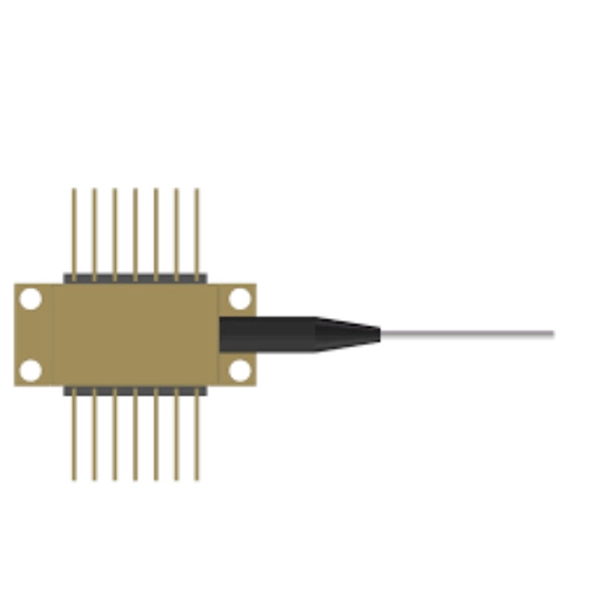
Comparison of high temperature resistance of polarization-maintaining fiber vs imported brands
This document presents a quick review of the two most prevalent methods currently used for the determination of the relevant figures of merit for PM fiber-based optical elements. The goal is to offer a more in-depth description Figure 1. Polarization-maintaining (PM) fibers are single-mode optical fibers that possess a high built-in birefringence, distinguishing them from standard single-mode fibers where birefringence is minimized but random. This strong birefringence defines two orthogonal principal axes — typically called the. Thus it is important to exactly align the polarization axis of the laser source with the polarization axis of the fiber e. The orientation procedures of high-quality polarization. Owing to their excellent resistance to environmental interference and high stability, all-polarization-maintaining mode-locked fiber lasers hold significant application value in various fields, including industrial processing, communications, medical applications, and military applications.
[PDF Version]
-
Performance comparison remote monitoring vs other types of dense wavelength division multiplexers
This article provides a detailed comparison of these three technologies, highlighting their key differences, advantages, and ideal use cases, empowering network professionals to make informed decisions for their specific needs. In the relentless pursuit of higher bandwidth and more efficient fiber utilization, wavelength division multiplexing (WDM) technologies are fundamental. But navigating the alphabet soup of CWDM, DWDM, MWDM, LWDM, and SWDM can be daunting. Coarse Wavelength Division Multiplexing (CWDM), Dense Wavelength Division Multiplexing (DWDM), and Shortwave Wavelength. Although both technologies function by multiplexing different wavelengths into a single fiber, significantly enhancing a fiber optic network's bandwidth and data capacity, they have some essential differences worth exploring. As a technical manager with many years of experience in the industry, I.
[PDF Version]
-
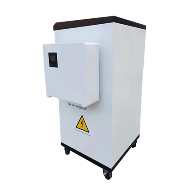
Modular energy storage cabinet remote monitoring technology support vs copper cable vs fiber optic cable
This article delves into the technical comparison between copper and fiber optic cables, exploring their unique properties, applications, and potential drawbacks. When energy storage cabinet remote systems prevented a 72-hour blackout in Texas last month, industry leaders finally stopped asking "if" and started asking "how fast". Copper cables are renowned for their superior conductivity, making them the. ocations are often difficult to reach and it might be too late to remedy the fault. Fiber has nearly unlimited bandwidth -- so once you deploy it, you can trust that it will outpace consumer demand for decades to come.
[PDF Version]
-
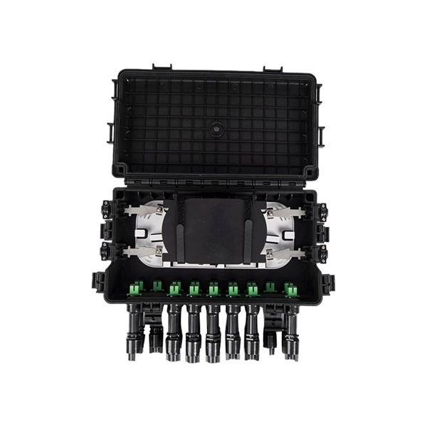
Comparison of High Temperature Resistance of Optical Splitter Boxes and Performance vs Copper Cables
We'll explore thermal limits for different fiber types, explain how temperature affects fiber performance, break down application-specific thermal challenges, and provide actionable tips for choosing the right temperature-resilient fiber. Optical fiber's ability to withstand extreme heat and cold directly impacts signal integrity, network reliability, and maintenance costs, especially in harsh environments like industrial facilities, outdoor installations, and data centers. Laboratory accelerated aging environments have long been used as a measure to predict field performance of optical fiber and cables'. Copper and fiber optic cables each offer distinct advantages and disadvantages that can impact performance, cost, and long-term efficiency. “Copper cables have traditionally served most network links between servers, routers, and switches,” explained. Many engineers struggle with performance drops in high-temperature environments. Harsh heat can degrade normal fiber optic cables, causing downtime, data loss, or expensive replacements.
[PDF Version]
-
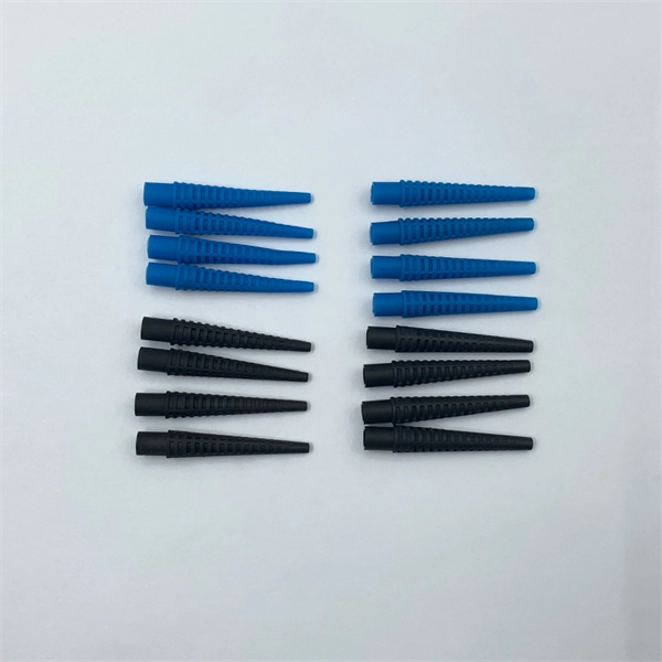
High Temperature Resistance of Optical Cable Spiral Tube for Distribution Network Automation vs Copper Cable
This blog post will delve into the significance of heat-resistant spiral binding for cables and how it enhances durability in demanding environments. Our high-temp cable selection features heat-resistant insulation materials like fiberglass, silicone, and TFE, ensuring reliable performance where standard. High temperature cables (also known as High Temp cables) represent a vast range of cables which continue to perform at increased and elevated temperatures. We supply a range of high temperature cables that are manufactured in accordance with various British and International Standards, including. Protective tubing refers to a flexible tubular wrap used to encase and shield individual cables or wire bundles. It provides an extra layer of protection against abrasion ensuring the longevity and integrity of the cables. The "UL Certified Spiral Tube" is a protective tube that excels in chemical resistance, cold resistance, and weather resistance. The maximum operating temperature is high, up to 250°C, and it has. Available in Pure Nickel (Nickel 200) or 27% Nickel Clad Copper conductors.
[PDF Version]
Telecom Racks & Cabinets
19-inch racks, wall-mount cabinets, open frames with high load capacity and seismic rating.
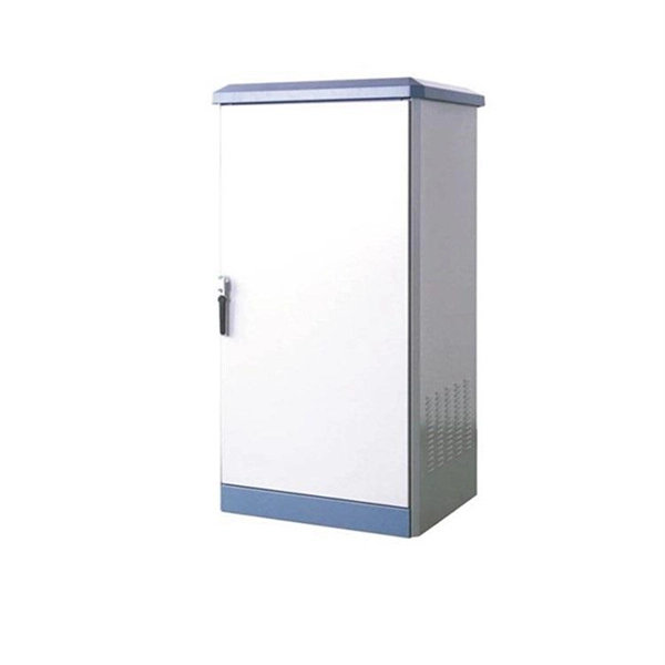
Outdoor Climate Cabinets
IP55/IP66 outdoor enclosures with integrated cooling/heating, -40°C to +55°C operation.
Smart PDUs & Power Distribution
Intelligent PDUs with remote monitoring, per-outlet switching, and environmental sensors.
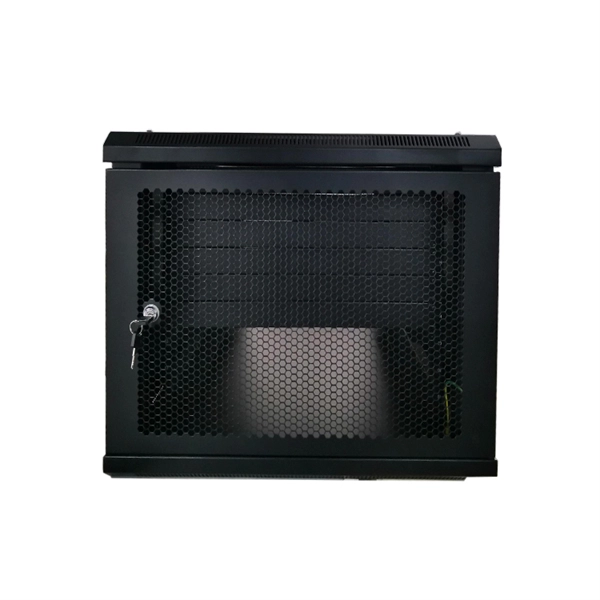
Shelters & Network Cabinets
Prefabricated telecom shelters, emergency comms shelters, and network cabinets with cable management.