-
National Standard for Angle Iron Cable Trays
The primary rulebook used in the safe use of cable trays is NEC Article 392. This is a description of how to select, install, and support these metal or plastic frames, on which electrical wires are installed. This standard specifies the requirements for nonmetallic cable trays and associated fittings designed for use in accordance with the rules of the Canadian Electrical Code (CEC) Part 1, and the National Electrical Code® (NEC). Covers construction and test requirements for. us-trations without notice. All illustrations, descriptions and technical information included in this document are provided as indications and can cable trays are equivalent. The flexibility and scalability of cable trays make them an ideal choice for environments where cable density and organization can. NEMA Standards Publication 1 (0$9 ( 6WDQGDUGIRU0HWDO&DEOH 7UD6VWHPV National Electrical Manufacturers Association NEMA Standards Publication VE 1-2017 CSA Group Publication CSA C22.
[PDF Version]
-
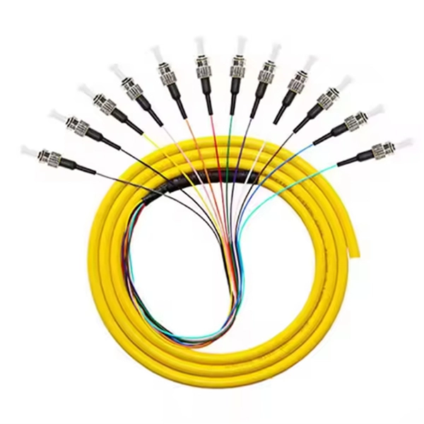
National Standard Optical Cable Sheath Wall Thickness
Fiber optic "cable" refers to the complete assembly of fibers, other internal parts like buffer tubes, ripcords, stiffeners, strength members all included inside an outer protective covering called the jacket. The optical fiber color coding shall be in accordance with EIA/TIA-598, "Optical Fiber Cable Color Coding. (FOA) was founded in 1995 to help develop the workforce to build the fiber optic networks to support a rapid expansion in communications and the Internet. The charter of the FOA was to promote professionalism in fiber optics through education, certification, and. However, when I started trying to find out where I got it from, it turned out that there were no requirements for sheath thickness in the IEC standards for HV and EHV cables. ASTM E119, Standard Test Methods for Fire Tests of Building Construction and Materials, is the test standard for determining the. This is the standard sheathing material for cables for outdoor use. It has excellent weathering resistance.
[PDF Version]
-
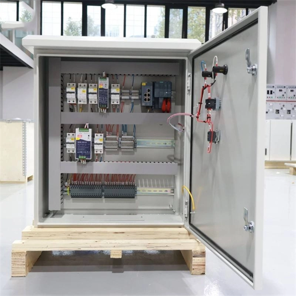
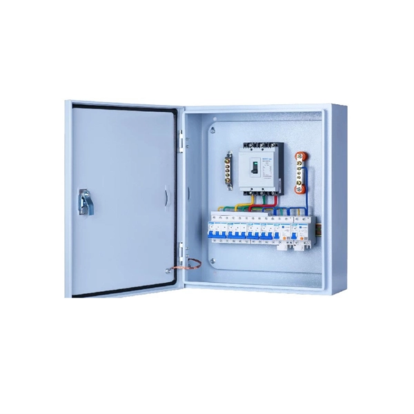
Standard Configuration of Photovoltaic Distribution Box
IEC 62548:2016 sets out design requirements for photovoltaic (PV) arrays including DC array wiring, electrical protection devices, switching and earthing provisions. The scope includes all parts of the PV array up to but not including energy storage devices, power conversion. The photovoltaic distribution box serves as a critical component in modern solar energy systems, acting as the central hub that manages and distributes electricity generated by solar panels. Photovoltaic (PV) systems (or PV systems) convert sunlight into electricity using semiconductor materials. It can also generate electricity on cloudy and rainy days from reflected sunlight. An. Technology Convergence Drives 2025 Market Leadership: The integration of AI-powered optimization, bifacial panels, and smart grid technologies positions PV arrays as the dominant renewable energy solution, with global capacity projected to reach 6,000-7,000 GW by 2030. This device plays a significant role in both residential and commercial solar installations, particularly when.
[PDF Version]
-
National Standard Certification for Cable Trays
The official rulebook for making cable trays is NEMA VE 1. It ensures that all the trays are robust, secure, and of the appropriate size. When a tray obeys these rules, it will be able to work even when belonging to some other factory or even being of a different lot. Addresses shipping, handling, storing, and installation of metal cable tray systems. Information on maintenance and system modification is also. NEMA, short for National Electrical Manufacturers Association, is the leading trade association for electrical equipment manufacturers in the United States. The flexibility and scalability of cable trays make them an ideal choice for environments where cable density and organization can. , is a welded wire-mesh cable management system made of high-strength steel wire. In addition, this document contains several references to provisions of the National Electric Code.
[PDF Version]
-
Standard thickness of distribution box material
According to national standards, the wall thickness of the low-voltage distribution box should not be less than 1. Designed by BAHRA, the Load Centers (LC) use the best selection of materials, cutting edge technology and class leading features to ensure safety, durability and performance. These Distribution Cabinets are to be outdoor type nd to be fabricated out of 2 mm GI sheet steel. Different types and uses of distribution boxes may have slightly different standard requirements, but overall, the box size above. ABB Mini Center Compact distribution board is the basis for development and growth in meeting all the demands for a successful future in residential, commercial, and infrastructure segments. The wide range of distribution boards enables each customer to select an individual and economical. All distribution boxes or distribution cabinets shall be made of cold-rolled steel plates complying with national standards. 1 This practice assists users in selecting appropriate performance characteristics of corrugated fiberboard or box construction, or both, commensurate with their user's needs for packing and distribution of goods.
[PDF Version]
-
What standard is used for the height of electrical distribution boxes
Wall-mounted boxes should be 4. This height makes it easy to reach without bending or stretching. Ground-mounted boxes should be raised 2 to 4 inches to avoid. The proper installation of a distribution box involves placing it at the right height to ensure safety and convenience. NEC Article 408 covers switchboards, switchgear, and Panelboards installation and applications. 26 (A) (1), (A) (2) and (A) (3). u2029 The dimension for height of working space for equipment operating at 600 volts (V), nominal, or less to ground and likely to require examination, adjustment, servicing or. This article provides an exhaustive examination of the principles and standards governing the height at which electrical panels should be installed, offering readers practical insights grounded in safety, accessibility, and compliance. The NEC, published by the. The National Electrical Code provision 110. Whether in a home or an industrial facility, this box keeps your electrical setup organized, functional, and efficient.
[PDF Version]
-
Features of National Standard PoE Switches
Let's explore these in detail: 1. 3af (PoE) Output Voltage: 44–57V (typically 48V) Max Power Per Port: 15. 95W (due to cable loss) Applications: Low-power devices like basic IP cameras, VoIP phones. 3at (PoE+) Output Voltage:. A: Standard PoE power supply (Power over Ethernet, referred to as PoE) is a technology that provides both power and network connectivity to remote devices such as IP phones and IP cameras over Ethernet cables without additional power lines. These devices can deliver data and electrical power to connected devices through Ethernet cables. But with different PoE standards— PoE (802. PoE technology has been widely used in many industries, such as security and surveillance.
[PDF Version]
-
Standard for Electrical Box Assembly in Suspended Platforms
The legal and latest version of the "Assembly & Operating Instructions for suspended platform system" are, on request, available at the supplier of your suspended platform system. Code of safe practices for suspended powered scaffolds Severe injury or even death can result from improper assembly or improper use of this suspended platform system. You. Ensure suspended platform safety with guidelines on inspection, operator training, fall protection, load limits, and emergency procedures for safe high-rise work.
[PDF Version]
-
National Standard Optical Cable Joint Fusion
This standard defines the equipment, methods, and practices used within the cable/broadband industry to obtain consistent low loss fusion splice connections between optical fibers. d suppliers of electrical construction services. Existence. In this guide, you will find a chronological description of the fusion splicing process, the principal technical standards, and answers to the real-life questions network engineers and procurement teams may have. Therefore, we will also touch on cost factors, risk management, and best practices in. The Fiber Optic Association, Inc. (FOA) was founded in 1995 to help develop the workforce to build the fiber optic networks to support a rapid expansion in communications and the Internet. The charter of the FOA was to promote professionalism in fiber optics through education, certification, and. Jointly developed with The Fiber Optic Association T h e FiberO pti c Association FOA Published by National Electrical Contractors Association NOTICE OF COPYRIGHT This document is copyrighted by NECA ISBN: 978-1-944148-17-1 ©2016.
[PDF Version]
-
Standard System for Energy Internet
EI is also known as “Enernet”, which is an Internet of energy (IOE). EI aims to transform energy production, storage, and transport. Energy Internet is a concept proposed to harness, control, and manage energy resources effectively, with the help of information and communication technology. This set of standards, embodied in a document titled " Internet Protocols for the Smart Grid Although most users and consumers know very. The German Federal Ministry of Economics and Technology also launched E-Energy (Internet of Energy) about the same time. From generation to transmission to distribution and consumption, the E-Energy paradigm emphasises digitally integrated, sustainable energy systems enabled by information and. This chapter presents the development of the Energy Internet throughout the history as an evolutionary solution based on modern technological development and needs, with the respect of its architecture, key features, and key concepts, such as energy router, prosumer, and virtual power plant.
[PDF Version]
-
Hungarian Standard Medium and Low Voltage Complete Set of Equipment
The core activity of our company is the installation, implementation of various low and medium voltage electrical networks and systems. We are qualified entrepreneurs of all electricity suppliers currently operating in Hungary (E. ON, NKM, ELMÜ-ÉMÁSZ). Our Ars Poetica is “Quality and Confidence”. Our business venture founded in 2010 is owned in 100% by Hungarian owners. Owing to our professional experience obtained in years, our customer-oriented attitude and business strategy, we have reached a dynamic growth in recent years. At Technopower, we offer. Customizable unit substations with primary voltage classes up to 38kV and secondary voltage class starting 5kV and below. Choose from Schneider Electric's expansive ranges of breakers and fusible.
[PDF Version]
-
Standard for Aviation Plugs in Level 3 Distribution Boxes
The primary purpose of this standard is to provide the requisite information to promote compatibility between aircraft electrical power, external electrical power, and the airborne equipment that uses that power, with MIL-STD-704 serving as the governing document. This standard is approved for use by all Departments and Agencies of the Department of Defense. The selection guidance in this. U. Department of Transportation Federal Aviation Administration Subject: FAA SPECIFICATION FOR L-823, Date: 04/17/00 AC No. : 150/5345-26C PLUG AND RECEPTACLE, CABLE CONNECTORS Initiated by: AAS-200 Change: __________________________________________ 1. For official status and latest revisions, see the Defense Logistics Agency ASSIST system. This data warehouse includes standardization documents with the designations of MIL, MIL-STD, MIL-PRF, MIL-DTL, FED, CID, JANS, MS, AND, USAF, DID, CID, UCF. IBILITY: Publications and forms are available for downloading or ordering o rements for electrical grounding systems, including systems for equipment grounding, lightning protection, and static protection. 43-6, 31 FR 9211, July 6, 1966.
[PDF Version]
-
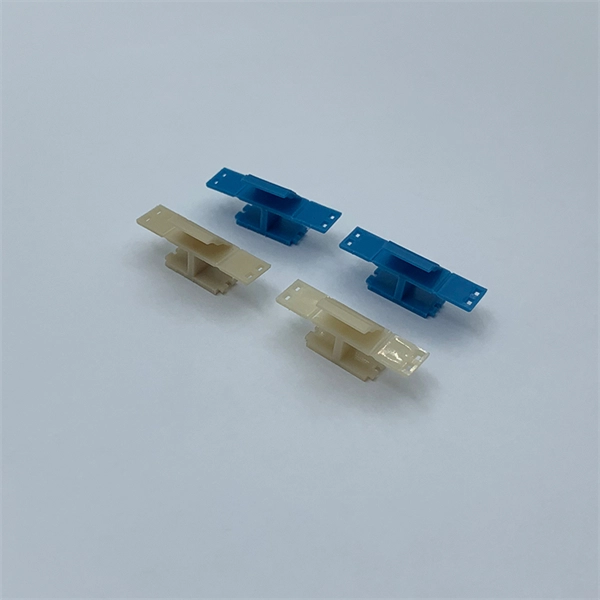
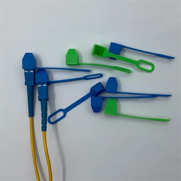
Standard Junction Box Fiber Fusion Method
In this guide, you will find a chronological description of the fusion splicing process, the principal technical standards, and answers to the real-life questions network engineers and procurement teams may have. Fusion splicing is the most widely used method of splicing as it provides for the lowest loss and least reflectance, as well as providing the strongest and most reliable joint between two fibers. This will typically be 250µm for bare fibers and 900µm for coated fibers. Therefore, we will also touch on cost factors, risk management, and best practices in. aces are essentially melted together. This process is also completed by a sophisticated tool called a Fusion Splicer, which aids in the alig ment, inspection, and curing process.
[PDF Version]
-
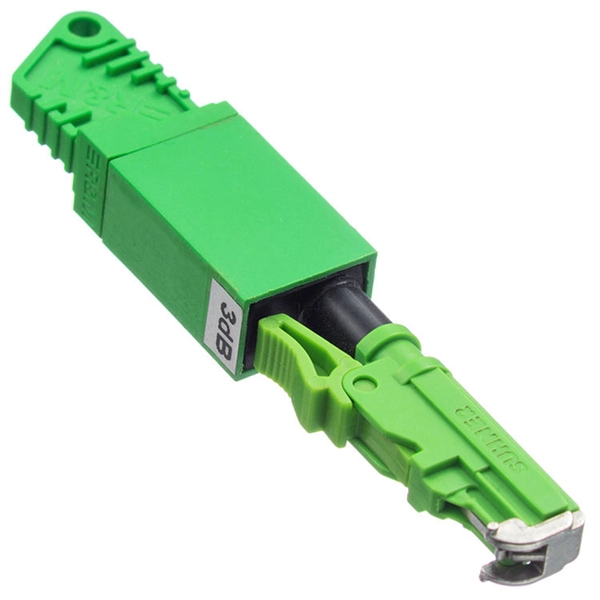
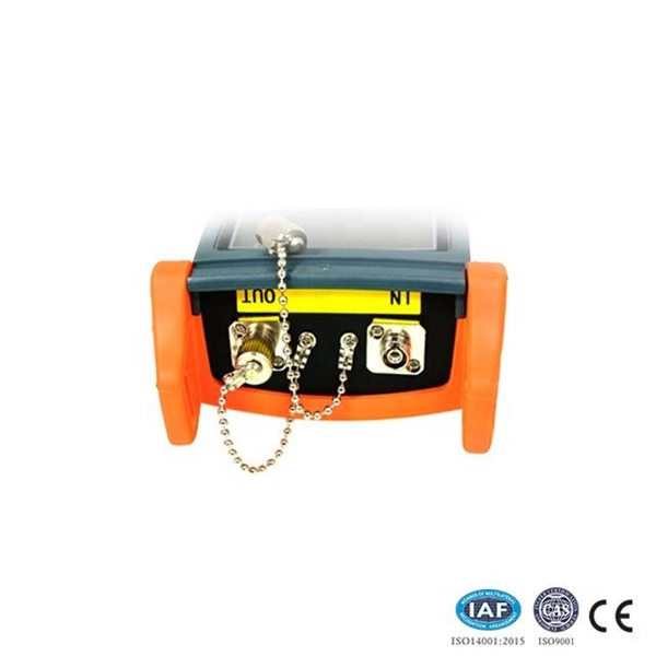
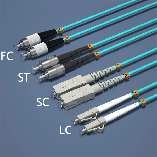
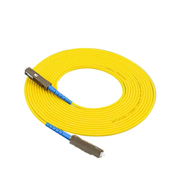
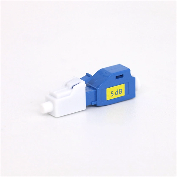
Multimode fiber optic splice loss standard
For multimode fiber, the loss is about 3 dB per km for 850 nm sources, 1 dB per km for 1300 nm. 5 dB/km max per EIA/TIA 568) This roughly translates into a loss of 0. Splicing is required to create a continuous path for light transmission from one fiber to another. Two different methods exist for splicing fibers: Typical splice loss values (the measure of loss in optical power across the splice point) are usually lower for fusion splices (typically less than 0. 1. To be able to judge whether a fiber optic cable plant is good, one does a insertion loss test with a light source and power meter and compares that to an estimate of what is a reasonable loss for that cable plant. The estimate, called a "loss budget" is calculated using typical component losses for. Acceptable dB loss for fiber depends on the component you're measuring: a single mated connector pair should lose no more than 0. 75 dB, a fusion splice should stay under 0. 5 dB per kilometer depending on the type and wavelength. The Contractor must utilize the correct equipment and testing techniques to gain acceptance, or the work cannot be approved. Optical fiber splicing is a critical.
[PDF Version]
-
Cable tray positioning ruler standard
62275 and UL 62275, the Standard for Cable Management Systems – Cable Ties for Electrical Installations, are based on the IEC 62275 standard. UL and CSA standards adopt the original IEC text and include additional national diferences to address safety. CSA C22. A properly designed and installed cable tray system will provide. Hubbell Take Off Support provides the contractor, engineer, end user a completed BOM, including all related products, counts, symbol legends and information required to price a project. Don't spend the many hours required to do counts and create BOMs for projects, rely on Hubbell's take off. association representing the major electrical equipment manufac-turers in the U. For proper installation, design, and maintenance, adherence to international standards is essential.
[PDF Version]
Telecom Racks & Cabinets
19-inch racks, wall-mount cabinets, open frames with high load capacity and seismic rating.
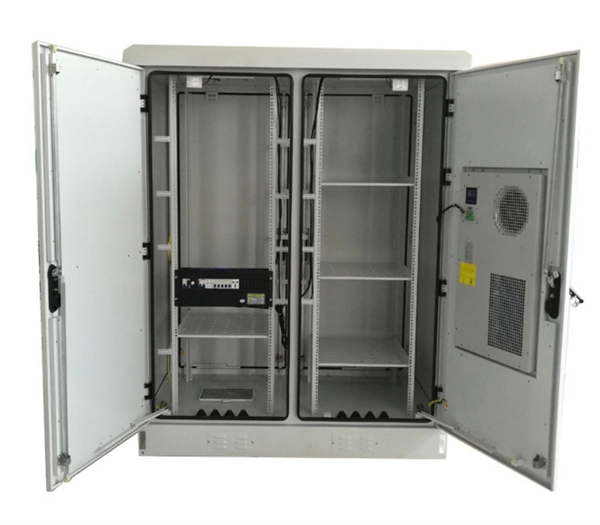
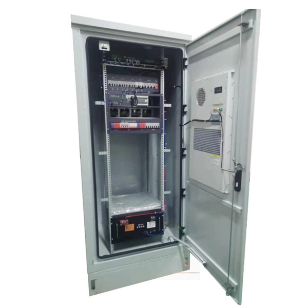
Outdoor Climate Cabinets
IP55/IP66 outdoor enclosures with integrated cooling/heating, -40°C to +55°C operation.
Smart PDUs & Power Distribution
Intelligent PDUs with remote monitoring, per-outlet switching, and environmental sensors.
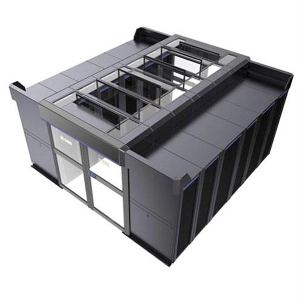
Shelters & Network Cabinets
Prefabricated telecom shelters, emergency comms shelters, and network cabinets with cable management.