-
Bridge erected in 26 seconds
On Thursday, a recently erected pedestrian bridge linking Florida International University's (FIU) Modesto A. Maidique Campus to the city of Sweetwater collapsed, killing at least six people and crushing an unknown number of cars. In May 2022, Ukrainian spotters watched something unfold on the Siversky-Donets River that would change how the Pentagon views the next major war, and why America is betting $252 million on a 23-foot b. more Audio tracks for some languages were automatically generated. Learn more M30 Bridge. PSA If you updated to KSP2 patch 4, Start a new campaign. It will drastically improve your fps It's been 6+ months since KSP2's release. Start now with a 30 Day FREE TRIAL to access all our premium members features, or start with our free Hand of the Week.
[PDF Version]
-
Calculation formula for cable tray supports and hangers
Cable tray support quantity can be calculated using a simple formula: Support Quantity = Total Length ÷ Support Spacing + 1 20 ÷ 2 + 1 = 11 supports In a typical project, a 20-meter cable tray with 2-meter spacing requires 11 supports. As a key structure supporting the cable tray, the accurate calculation of the support quantity directly affects construction costs, efficiency, and safety. Follow these simple steps: Define Tray Dimensions: Enter the width and depth of your planned cable tray (in mm or inches). Select Fill Standard: Choose 40% for power cables (NEC compliant) or 50% for. The formula to calculate the cable tray capacity is: [ CTC = text {floor}left (frac {W cdot H cdot FR} {CA}right) ] Where: ( CTC ) is the cable tray capacity (number of cables). This article details everything from permitted uses and cable types to fill capacities and. Table 1: IEC Common Ladder and Tray Dimensions Note: Quantities above are approximate and assume single-layer horizontal mounting without fill derating. The International Electrotechnical Commission (IEC).
[PDF Version]
-
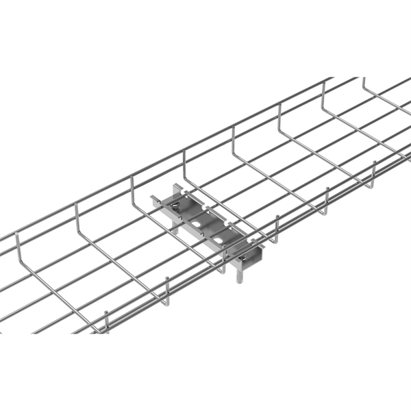
Methods for fixing ladder-type cable tray supports
Mark the support, fix the threaded rod supports with appropriate metal plugs, and then fix the 'L' angles / Slotted 'C' channels with nuts. The following recommendations are intended to be a practical guide to ensure the safe and proper installation of cable ladder and cable tray systems and channel support and other support systems. Cable ladder systems and cable tray systems shall be manufactured in accordance with BS EN 61537, channel support. This guide covers the critical steps, from selecting the right electrical cable tray and performing accurate cable fill calculations to managing a safe cable pull through and ensuring all bonding and grounding requirements are met. For licensed electricians, mastering these principles is essential. When developing our cable support OBO can offer reliable solutions for systems, three attributes are at the routing and fastening cables securely core of what we do: efficiency, resil- for each of these installation challeng-ience and safety. es in the industrial environment. The Ladder Tray features light, rugged, tubular steel construction.
[PDF Version]
-
How are the supports used to secure cable trays fixed
Support Methods: Common support methods include trapeze hangers, which are used for ceiling suspensions, and cantilever wall brackets, which are mounted directly to walls for runs along vertical surfaces. The choice depends on the building structure and the planned tray route. Why Are Cable Tray Supports Important?The hardware in this section covers the systems that physically carry, support, and secure cable in the field. Trays, ladders, strut, clamps, brackets, magnetic mounts, and the fittings that tie them together—each item defined so you can identify it, spec it, and use it correctly on the job. Whether you're managing voice, data, or electrical cables, ensuring your trays are installed correctly is essential to keeping everything neat, secure, and functional.
[PDF Version]
-
Techniques for laying out tunnel cable tray supports
Mounting Clamps: These are great for securing cable trays to walls or ceilings. Article Summary: A compliant cable tray installation requires a thorough understanding of NEC Article 392, proper structural support, and precise installation techniques. This guide covers the critical steps, from selecting the right electrical cable tray and performing accurate cable fill. Cable trays provide a support structure to lay out cables across hundreds of meters, without the likelihood of sagging or becoming tangled, or even getting in contact with the rough tunnel walls. This improves overall electrical cable organization in tunnels, making inspections and repairs. ass reinforced polyester) cable trays. These solutions provide optimum safety, flexibility and excellent corrosion resistance for ety lighting, signs, ventilation, etc. During forklift offloading on uneven ground, one must exercise extreme caution to prevent load shifting. Before starting, ensure you have.
[PDF Version]
-
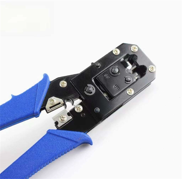
How to match cable tray shaft supports
It is the quickest way to attach tray to support, utilizing a washer support and self threading screw. Corner Splice and Radius Corner Splice are used when tray sections are joined to make a 90 degree horizontal transition. This guide covers the critical steps, from selecting the right electrical cable tray and performing accurate cable fill calculations to managing a safe cable pull through and ensuring all bonding and grounding requirements are met. For licensed electricians, mastering these principles is essential. According to DIN EN 61537, a cable support system is used to support and house cables. This includes both the cable load and environmental loads like wind, snow, ice (See Cable Tray Strength and Load Capacity section in this guide). Why Are Cable Tray Supports Important?maintain spacing or to keep cables in place when the tray is ect the minimum bend ra-dius for cables as they exit the bottom of the cable tray.
[PDF Version]
-
Spacing of T-type cable tray supports
Cable Management Tray Size: Choose a tray size that will hold the desired amount and length of cable. The National Electrical Code (NEC) covers many aspects of cable tray supports and fittings. The National Electrical Code is a set of principles designed to promote public safety and welfare, as well as safeguard public health by regulating the design and operation of electrical facilities and. maintain spacing or to keep cables in place when the tray is ect the minimum bend ra-dius for cables as they exit the bottom of the cable tray. A rung spacing of 6 to 9 inches (150 to 230 mm) is preferable when the cable tray cont d for instrumentation and control applications that require. Understanding cable tray spacing is key to meeting safety regulations and maintaining system performance. Proper installation can significantly reduce. When developing our cable support OBO can offer reliable solutions for systems, three attributes are at the routing and fastening cables securely core of what we do: efficiency, resil- for each of these installation challeng-ience and safety. es in the industrial environment. The Ladder Tray features light, rugged, tubular steel construction.
[PDF Version]
-
Advantages and disadvantages of various cable tray supports
This guide breaks down cable tray applications by industry, explaining why they are used, where they fit, and which types work best. If you're planning a project, this will help you make faster, more practical decisions. The following table compares ladder and perforated cable trays based on design, application, airflow, cost, and cable support: Cable trays offer several key benefits: Easy Installation: Quick and easy to install. No special training or expertise is needed. Easy Maintenance: Since cables are. Cable tray systems are alternatives to wire ways and electrical conduit, which completely enclose cables. They are widely used across industries such as construction, manufacturing, data centers, and more. They provide excellent air.
[PDF Version]
-
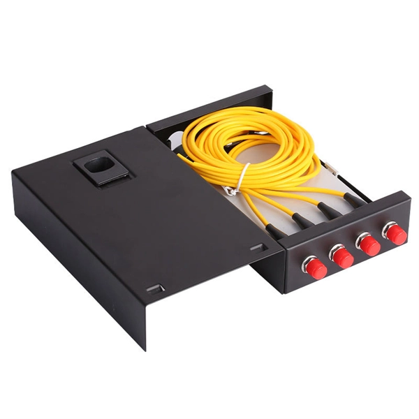
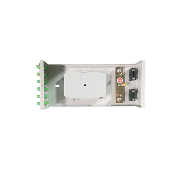
Optical power meter red light supports remote operation
The Red Light OLP integrates the capabilities of both an OTDR and an OPM in a single device, making it a versatile and convenient solution for network technicians. It utilizes red light technology, which allows for accurate power measurement and characterization of fiber. PG-OPM202 series power meter PG-OPM2020 Hand-held optical power meter, red-light integrated machine series products are mainly used for continuous optical signal power measurement, optical fiber link loss testing and optical fiber line on-off testing. Controlled with a single microprocessor, it is fully functional. Designed for fiber professionals, it covers 7 calibrated wavelengths and is compatible with SC, FC, and ST connectors. GOOD PERFORMANCE: The power meter supports fast and accurate measurement without waiting for warm up, with relative power calculation and self. STD800 series mini Optical Power Meter and red light all-in-one machine series are controlled by single-chip microprocessor but multifunction. The whole machine has automatic shutdown function, three red light modes, backlight display.
[PDF Version]
-
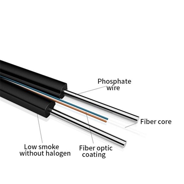
How many meters is one section of fiber optic cable pole
The basic pole distance is 50m, which can be adjusted to 60m according to the terrain of mountainous areas. In case of special sections, crossing obstacles or roads or railways, the pole height of 8m, 9m, etc. ASU cable offer a wider range of span. Fiber optic aerial pole route mainly consists of aerial fiber optic cables, required number of poles, guys, stranded metallic wires, braced poles, and other necessary components that are required for installation. The aerial fiber optic pole route is arranged to keep the standards of pole span and. In the ever-expanding universe of fiber optic networks, where speeds reach 800G and beyond while global FTTH connections surpass 2. Commonly referred to as figure 8 cable, figure 8. OR FTTP has been put in but runs to the nearest telegraph pole rather than following the existing setup, this is around 70m away in a straight line and has line of sight issues with tree in the way.
[PDF Version]
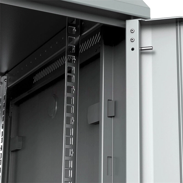
Telecom Racks & Cabinets
19-inch racks, wall-mount cabinets, open frames with high load capacity and seismic rating.
Outdoor Climate Cabinets
IP55/IP66 outdoor enclosures with integrated cooling/heating, -40°C to +55°C operation.
Smart PDUs & Power Distribution
Intelligent PDUs with remote monitoring, per-outlet switching, and environmental sensors.
Shelters & Network Cabinets
Prefabricated telecom shelters, emergency comms shelters, and network cabinets with cable management.