-
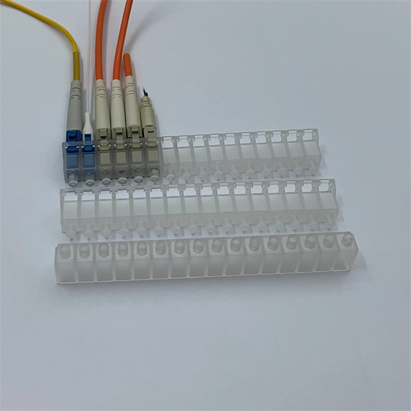
Ireland Polarization-Maintaining Fiber Multimode Selection Guide
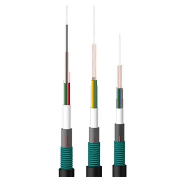
Here, we use the same PM fiber and non-reciprocal phase shifter to design two different devices, which are capable of acting as effective NPE saturable absorbers (SAs) in two all-PM linear cavity fiber lasers. Polarization-maintaining (PM) fibers are single-mode optical fibers that possess a high built-in birefringence, distinguishing them from standard single-mode fibers where birefringence is minimized but random. Corning offers the broadest portfolio of PANDA PM fibers from wavelengths of 400-1550 nm and designs such as High NA and Flame Retardant coatings., photonic crystal, double clad, and rare-earth doped) fiber. Choose from FC/PC, FC/APC, or SMA connectors. The product offering includes standard telecom single-mode and multimode optical fiber, either graded-index or step-index, specialty fibers such as polarization preserving fiber, high power delivery. Different types of polarization-maintaning fibers are designed depending on the geometry of the stress elements: “PANDA“ fibers, “Bow-Tie“ fibers or “Oval-Inner Clad“ fibers.
[PDF Version]
-
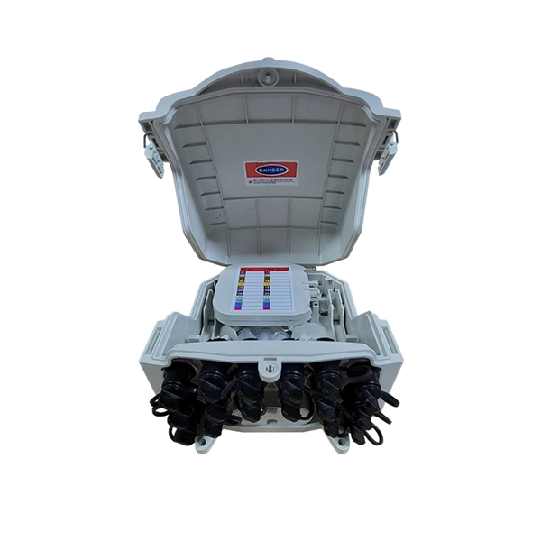
Guatemala CIF price butterfly-shaped fiber optic cable multimode
This guide compares multimode cable prices across OM1–OM5 and explains what really moves the number: fiber grade, fiber count, jacket rating, and whether assemblies are factory-terminated. After three years of growth, the Guatemalan market for optical fibers, bundles and cables decreased by X% to $X in 2024. Overall, consumption, however, showed a mild expansion. After. Single-mode Butterfly Fiber Optic Cable: Ideal for long-distance communications, it enables a single ray of light to travel through the core, thus facilitating longer transmission distances with minimal signal loss. In 2025, overseas shipments of optical.
[PDF Version]
-
What is the optimal length for a multimode fiber optic patch cord
For a typical office or datacenter, standard-length patch cords in the range of 2m to 10m are often all that is needed. A patch cord is an essential component of a fiber optic setup, being cost-efficient while being compatible with most devices and easy to find in stores. It directly impacts signal integrity, data transmission speed, and network latency. As such, understanding the implications of cable length on network performance is crucial for. This is why a common length like the 2m LC LC patch cord, a 3m or even 5m patch cord is widely used, for instance, they strike a balance between flexibility and performance. However, the dispersion-compensating fibers can support more than 200 kilometers.
[PDF Version]
-
What is the maximum transmission distance of multimode fiber optic cable in meters
Because of this, more data can pass through the multimode fiber core at a given time. The maximum transmission distance for multimode fiber cable is around 550m at the speed of 10Gbps. Multimode fiber optic cables are designed to carry multiple light modes simultaneously, each taking a different path or mode through the fiber. The maximum transmission distance for multimode fiber cable is around 550m at the speed of. Multimode Fiber (MMF) has a core diameter, typically 50–100 micrometers, has ability to transfer multiple modes of light through the fiber core, uses lower-cost electronics (LED, VCSEL) operates at the 850 nm and 1300 nm wavelength and is used for short distance interconnections (up to 550m). Fiber optic cable can be run anywhere from 300 meters up to 80 kilometers (roughly 50 miles) depending on the cable type, transceiver used, and network standard. OM1 fiber has a core diameter of 62. With a 200 MHz/km bandwidth, OM1 fiber can transmit up to 275 meters for 1 Gigabit. OM1 fiber can transmit data up to 33 meters at a data rate of 1 Gbps, while OM5 fiber can transmit data up to 550 meters at a data rate of 100 Gbps.
[PDF Version]
-
Can single-mode fiber optic cable be converted to multimode
Easily connect different fiber types and wavelengths to convert Single Mode to Multimode (SM to MM), or extend the distance of Multimode networks. But what happens when you need to connect an existing multi-mode campus network to a new single-mode service provider link? You can't just splice them together. This is where fiber conversion comes in. This guide will break down the professional methods to achieve seamless single-mode to multi-mode. Single-mode (SMF) and multi-mode fiber (MMF) use different core sizes, sources and wavelengths. Understanding the compatibility constraints prevents costly downtime and troubleshooting.
[PDF Version]
-
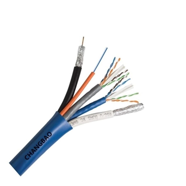
How many data points can a 4-core multimode fiber optic cable support
OM4 fiber supports 10G, 40G, 100G, and even 400G Ethernet over extended distances compared to OM3, making it ideal for future-proof network infrastructure. Greater reach than OM3, reducing the need for signal. The number after OM—2, 3, 4, or 5—indicates the amount of data the fiber can carry and the distance it can maintain that speed. With that in mind, let's look at the four main multimodal grades in use today. It works with LED. This guide walks you through the simple decision steps engineers use, the common strand counts on the market, and clear rules-of-thumb for different project types so you choose a cable that fits both today's needs and tomorrow's growth. Begin by listing what the network must support now and in five. OM4 multi-core ribbon fiber optic cable is a high-bandwidth, laser-optimized multimode fiber solution designed for ultra-high-speed data transmission in data centers, enterprise networks, and high-performance computing environments. The ribbonized structure combines multiple fibers (e. Understanding Fiber Cores: Core: The central glass fiber that transmits light signals.
[PDF Version]
-
Fiber Dispersion Single-Mode and Multimode
The document discusses the dispersion analysis in optical fibers, specifically focusing on single-mode and multimode fibers. This guide explores the key factors affecting fiber optic transmission distance and provides practical selection guidelines for a stable and cost-effective network deployment. Dispersion. Dispersion is the process through which a light pulse spreads out over time as it moves down the fibre.
[PDF Version]
-
How much does it cost to fuse one core of multimode fiber
The exact price hinges on splice complexity, fiber type (single-mode vs multimode), jacket condition, and whether the repair occurs on a backbone, distribution, or customer-facing link. Per-splice pricing often ranges from $200 to $600, depending on the equipment and skill. Typical cost range for a standard fiber optic repair spans from $1,300 to $11,000, with most projects in the $2,500–$6,000 band. The "per splice" rate is the most. The cost of splicing fiber optic cables can vary significantly based on several factors, including the type of splice, the equipment used, the location of the job, and the expertise required. Understanding these factors can help businesses and individuals budget effectively for fiber optic. Adtell Integration is capable of supporting your fusion splicing requirements whether they require Singlemode, Multimode, or Ribbon Splicing. Commercial building installations with 100-200 network drops generally range from $15,000 to $30,000. The main cost drivers are materials, installation time, and environmental factors that affect trenching, conduit, and terminations.
[PDF Version]
-
Multimode fiber optic cable has one side working and the other side not working
99% of the time, the problem is fiber polarity — specifically, Transmit (Tx) talking to Transmit and Receive (Rx) talking to Receive instead of Tx ↔ Rx. Good news: it's incredibly easy to understand and fix once you know the “two-lane highway” rule. The issue is when I plug multimode fibre in the module the link doesn't come up. Any reasons why it is happening. Why multimode fibre is not working with Multimode SFP Module? Someone suggested because MM. Or it could be caused by the quality of the connector itself, such as poor end-face geometry that doesn't pass the parameters defined by IEC PAS 61755-3 standards, including angle of the polish, fiber height, radius of curvature or apex offset. A more common cause is poor field termination that. Fiber optic networks are celebrated for their speed and reliability, but even the best systems can encounter problems. When issues like signal loss, slow speeds, or intermittent connectivity arise, systematic troubleshooting is key. These networks are the backbone of modern data transmission, offering incredible speeds and bandwidth. While fiber provides greater reach and bandwidth than copper, you may be.
[PDF Version]
-
Oman Multimode Fiber Fusion Splicing Quotation
Get competing quotes from suppliers, lenders or both. SPEED MEETS PRECISION - Achieve flawless fiber splicing in just 9 seconds! LIGHTWEIGHT PORTABLE - Designed for on-the-go professionals—carry it anywhere! VERSATILE CONNECTIVITY - Seamlessly splice various optical fibers with ease. USER FRIENDLY INTERFACE - Bilingual instructions ensure everyone can. The new Single fiber optic Fusion Splicer of SUN Telecom SUN-FS930 is a small, compact and lightweight unit featuring the very latest in core alignment splicing technology. OF-800 Mini FTTX Fusion Splicer Features: 2. 5 inch LCD color display Small volume, light weight Suitable for science research. There are two primary methods of splicing fiber optic cables: fusion splicing and mechanical splicing. Each method has distinct characteristics and costs associated with it. *The prices on this table are only estimates, and are based on actual Fusion Splicer quotes submitted by KWIPPED Suppliers in the last 12 months. The main cost drivers are cable grade (indoor vs outdoor, riser vs plenum), fiber type (single-mode vs multimode), connectorization, and installation length. This guide presents cost ranges in.
[PDF Version]
-
What are the standards for multimode fiber optic patch cords
3‑E “Optical Fiber Cabling and Components Standard” was developed by the TIA TR‑42. Scope: This Standard specifies performance, transmission, and test and measurement requirements for premises optical fiber cable. This guide cuts through the jargon: single-mode vs multimode, LC vs MPO, UPC vs APC, and every specification that actually matters when you're spec'ing out a real deployment. Whether you're cabling a new AI training cluster, upgrading a campus backbone, or just replacing aging patch cords in a. This article provides a comprehensive overview of international standards governing fiber optic cables, patch cords, MPO/MTP data center solutions, FTTA assemblies, and connectors. They act as the critical link for interconnecting devices like optical switches, servers, and distribution frames.
[PDF Version]
-
Maximum loss of multimode fiber at 1300nm
For multimode fiber, the loss is about 3 dB per km for 850 nm sources, 1 dB per km for 1300 nm. 5 dB/km max per EIA/TIA 568) This roughly translates into a loss of 0. 1 dB per 300 feet (100 m) for 1300 nm. 35 dB / Km at 1310 nm, which with a typical link loss of 20 dB, gives a maximum link length of 57 Km. The lowest loss wavelngth region is around 1550 nm. Best performance is achieved with for example Corning SMF-28® ULL with <0. 75 max per EIA/TIA 568) When testing cable plants per OFSTP-14 (double ended), include connnectors on both ends of the cable when using the 1-cable reference For other options see the. ion for the entire fiber run. Attenuation is a function of wavelength and needs to be specified for the etween a “1” and “0”. The goal is to minimize this loss as much as possible to ensure. This test will measure the loss of a fiber optic cable, singlemode or multimode, including connectors on each end individually. The same procedures may be used to calculate the.
[PDF Version]
-
Multimode fiber optic fusion splicing procedure settings
Learn how to splice fiber optic cable using fusion splicing with this complete step-by-step guide. 652), cost analysis, and FAQs for network engineers and installers. Fusion splicing is the most widely used method of splicing as it provides for the lowest loss and least reflectance, as well as providing the strongest and most reliable joint between two fibers. The guide provides the complete workflow, covering safety precautions, tool selection, fiber preparation, fusion operation, quality control, and. In this guide, you will find a chronological description of the fusion splicing process, the principal technical standards, and answers to the real-life questions network engineers and procurement teams may have. Look at the slide graphics and then read the notes below. If you have your own equipment, do the recommended exercises.
[PDF Version]
-
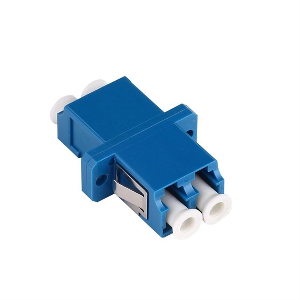
Fiber optic single-mode and multimode connection diagrams
This template showcases a professional layout for Fiber-to-the-Home and Fiber-to-the-Building setups. It visualizes the connection between a central office and various end-user locations. That makes picking between single mode and multimode fiber optic cables an. A fiber optics network diagram illustrates how high-speed data travels from an internet service provider to end users. By using light signals, fiber optics provide faster speeds and better reliability than. Fiber Optic connectors and cables are present in nearly every communications project that we might sell into, be it a DAS installation or a Base Station with wireless backhaul, you can be certain that fiber jumpers and cabling are being used somewhere in that network.
[PDF Version]
-
Multimode fiber optic splicing failed
Systematic approach to diagnosing fiber optic link loss in industrial communication networks. Covers OTDR testing, connector inspection, splice evaluation, bend loss identification, and repair procedures for single-mode and multimode fiber systems. The estimate, called a "loss budget" is calculated using typical component losses for. Splicing is required to create a continuous path for light transmission from one fiber to another. 1. I have SFP-10G-SR Multimode module connected to two switch. Any reasons why it is happening. The guide provides the complete workflow, covering safety precautions, tool selection, fiber preparation, fusion operation, quality control, and. The performance of a fiber optic splice is determined by a number of factors, including the quality of the fiber, the cleanliness of the splice, and the techniques used to make the splice. Intrinsic factors, such as the refractive index of the fiber, are those that are inherent to the fiber itself. About a week later modem goes offline and the line tests -49.
[PDF Version]
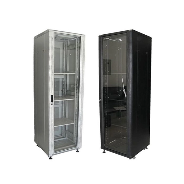
Telecom Racks & Cabinets
19-inch racks, wall-mount cabinets, open frames with high load capacity and seismic rating.
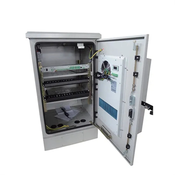
Outdoor Climate Cabinets
IP55/IP66 outdoor enclosures with integrated cooling/heating, -40°C to +55°C operation.
Smart PDUs & Power Distribution
Intelligent PDUs with remote monitoring, per-outlet switching, and environmental sensors.
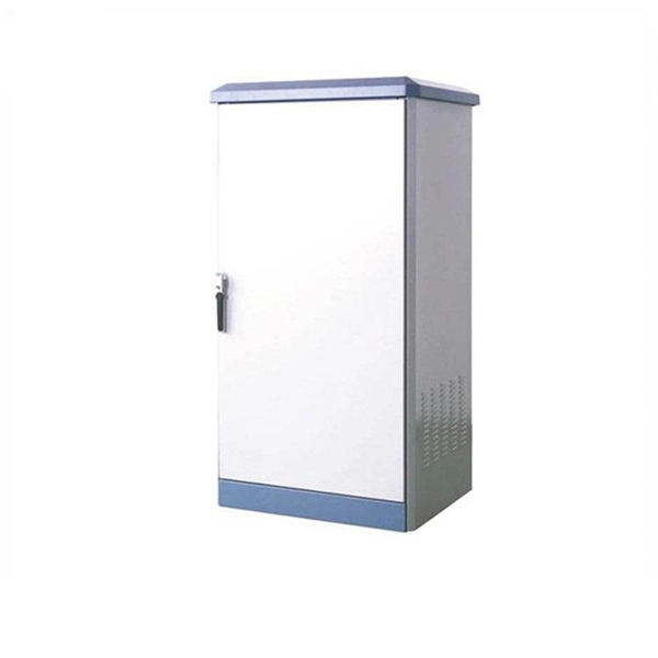
Shelters & Network Cabinets
Prefabricated telecom shelters, emergency comms shelters, and network cabinets with cable management.